Posted by
Unknown
at
10:34 AMon Sunday, January 5, 2014
Hi, As I'm starting with CADSoft Eagle software, I wanted to make a simple 2 motor driver board. This board can control 2 DC motors using the L298 circuit from ST.
You can find the complete data-sheet of the circuit here
Posted by
Unknown
at
12:03 PMon Saturday, January 4, 2014
The STM32F4 discovery is a wonderful board but it is really not freindly when testing with all its ugly male connectors that it is impossible to put it in a lab board.
I don't know if anyone did this before, but I made a small adapter in eagle for this board so it can be easily integrated with other test or prototyping project or it can be simply used in a hole PCB board.
Hi, Stepper motors are very commun in many applications, they are widely used in printers scanners and many other equipements thanks to their easy control.
I really advice you to understand how bipolar stepper works before testing the following code. Start from here !
The following code is for controlling a bipolar stepper motor using STM32F4 discovery board. I used a l293D for power interface between the stepper and the board like the following image:
And The I used this simple code to control my stepper in one direction with fixed speed using half step control.
Posted by
Unknown
at
1:07 PMon Thursday, January 2, 2014
Hello, This time I'll give you a short tutorial about how to use timers with the STM32. Timers are very useful when it comes to make a precise period of time independantly from your main loop execution.
The stm32F4 has many timers each one with a specific need. I'm just going to use the Timer 2 to make an interruption each 0.25 sec. I use a C# program to calculate what values to put in the prescaler and the periode to get my required interruption time. https://www.mediafire.com/?bq21q5qd7frcvba
The code has comments in it but if there is something that is not clear explained in the comments below, I'll be happy to answer.
void TIM2_IRQHandler(void){ static short i = 0; if (TIM_GetITStatus(TIM2, TIM_IT_Update) != RESET) { TIM_ClearITPendingBit(TIM2, TIM_IT_Update); GPIO_WriteBit(GPIOD,GPIO_Pin_13,i++); GPIO_ToggleBits(GPIOD, GPIO_Pin_14); } }
Posted by
Unknown
at
10:48 AMon Wednesday, October 9, 2013
We really need to integrate ourselves in the middle of social life, a person that cannot integrate in his society would be qualified as non normal or with no regular behavior. The fact is, that integrating in the society is a very relative concept, a person that cannot integrate himself in a specific society could be the most popular in another society, and we take the example of gamers or real geeks that bunch of guys that are so addicted to a video game or hacking computer software, have real problem with integrating within a society where the one who can use MSWord is qualified as a one who masters the computer. But the same Geeky person would be so popular in a society of geeks.
Here we go back to the point that in order to be popular or at least can integrate in a society, a person MUST share with the society its common believes, practices, way of thinking and looking to the world. To integrate with a society a person must talk like they talk even if there is actually nothing wrong with hes talking and way of reasoning, a person must joke like they do, eat like they do even if it'is not healthy for him to eat the food they eat or the way they eat not eating like them take a -1 from his popularity mark.
The problem is not integrating could be very harmful for some people, the fact that they loose connection with their entourage and surrounding colleagues, the fact that they are not respected or acknowledged for what they do best. For example a person who masters fishing would have no value in a society of hunters. And here we conclude that to integrate in a society, you must actual do something that is relevant and useful for them, otherwise a person with deviated skills cannot easily integrate with a society.
But any person in the world no matter how intelligent, crazy, ugly, beautiful, rich or poor need to have people surrounding him, that can talk with him ask for him and worry about him. It is a natural need and it's very harmful to take it from someone which hes only curse that he was born with a deviated skills.
So any person in this world must be conscious of this fact, and therefore open his mind to different ideas and different believes. respect the other competence even if it is not relevant to him it could be relevant for someone else, it could help other societies. Any person should not judge other people way of thinking as bizarre or weird, he could actual look more bizarre in another Time and Place Circumstances.
Finally, I would like to invite you to be more opened with weird people, they are actually more interesting than the typical believes.
Posted by
Unknown
at
5:22 PMon Friday, September 20, 2013
LCD can be a very useful part in any microcontroller based project. It helps to monitor variables and program status with simple texts or numbers.
For this application I used a JHD 162 A alphanumeric LCD, like the picture above.
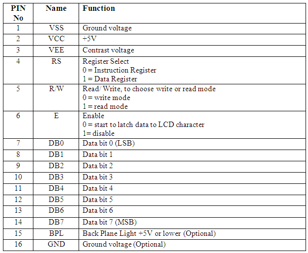
It hast 16 pins specified like this
VEE is used for contrast, so attache it to a potentiometer and choose your best contrast. Or simply plug it to 5V if you need maximum contrast.
D0, D1, D2, D3 are grounded
I managed to find a library for STM32VL, so I needed to bring some changes to it before it works. This library works both for JHD 162A and the hd44780.
lcd_hd44780.h
//****************************************************************************** // THE SOFTWARE INCLUDED IN THIS FILE IS FOR GUIDANCE ONLY. // AUTHOR SHALL NOT BE HELD LIABLE FOR ANY DIRECT, INDIRECT // OR CONSEQUENTIAL DAMAGES WITH RESPECT TO ANY CLAIMS ARISING // FROM USE OF THIS SOFTWARE. //******************************************************************************
//----------------------------------------------------------------------------- void lcd_writebinary(unsigned int var, unsigned char bitCount) { signed char i;
//Get fifth char ch = a%10; //if(ch || first) //you dont need to check las one if ch is 0 then just display it, unless you dont want to then uncomment this line ("//q" line too) lcd_writedata(48+ch); // lcd_str(intToStr(n)); }
Posted by
Unknown
at
1:51 PMon Monday, August 12, 2013
This is my first android application, it consists of something that I actually need during making electronic projects where there are so many resistors in the table and I can't just figure out the value of each one of them at a glance. Resistors used code colors, and each color according to its position has a specific value.
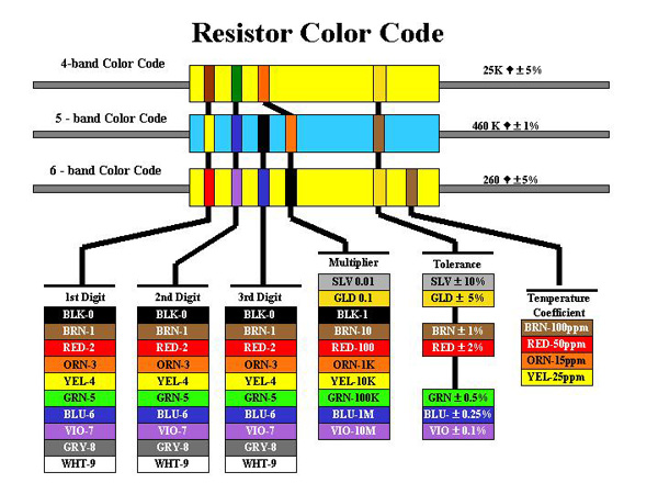
A resistor can have 4, 5 or 6 color bands just like the following picture:
Each color rank have a specific meaning in each Resistor type. For example the third band (from the left) of a 4 band resistor is a multiplier digit, but in the 5 band resistor it is the unity digit.
The previous picture shows a resistor with 4 color bands, organized as follow (from left to right)
Brown, Black, Red, Gold
10*10^ 2 +/- 5% = 1K ohm with 5% tolerance
For more information about how to calculate resistor color code, please refer to this wonderful wekipedia article: http://fr.wikipedia.org/wiki/CEI_60757 I actually use this mnemonic in french "ne mange rien ou jeuner voila bien votre grande bétise" to remember the mean of each color in the resistance' but sometimes that could be very confusing, so I thought to create an android app that help with that. I know that there is many android app doing that, but I did wanted to learn android too :D
The Android application:
In the Main activity, there are 3 buttons for each kind of resistor:
Each button open a new Activity through a simple intent in its OnClickListener() as follow:
Posted by
Unknown
at
8:34 AMon Monday, July 15, 2013
I've made some experiments using the STM32F3 discovery board, which is amazing by the way, and the mems(Micro ElectroMechnical Systems) in the board.
For more information about the board check this link where you will find all the technical hardware and software examples made with many IDEs. The main idea of this article is to make a standalone IMU (Inertial Measurement Unit) using only the STM32F3 board, because it has all the necessary hardware for making a complete 9 DOF IMU.
To do so I need to read both of the Gyroscope and the accelerometer data collected in a way so I can send later to the PC using VCP (USB CDC).
I started with the VCP example for the STM32303c eval board, you can find here And then I add both of stm32f3_discovery_lsm303dlhc.c and stm32f3_discovery_l3gd20.c, this two file could be found in the utitli folder of the firmware support for the STM32F3 board can be found here.
Then later I found this great files to give more abstract function to deal with the mems.
#define LSM_Acc_Sensitivity_2g (float) 1.0f /*!< accelerometer sensitivity with 2 g full scale [LSB/mg] */ #define LSM_Acc_Sensitivity_4g (float) 0.5f /*!< accelerometer sensitivity with 4 g full scale [LSB/mg] */ #define LSM_Acc_Sensitivity_8g (float) 0.25f /*!< accelerometer sensitivity with 8 g full scale [LSB/mg] */ #define LSM_Acc_Sensitivity_16g (float) 0.0834f /*!< accelerometer sensitivity with 12 g full scale [LSB/mg] */
/** * @brief Calculate the angular Data rate Gyroscope. * @param pfData : Data out pointer * @retval None */ void GyroReadAngRate (float* pfData) { uint8_t tmpbuffer[6] ={0}; int16_t RawData[3] = {0}; uint8_t tmpreg = 0; float sensitivity = 0; int i =0;
L3GD20_Read(&tmpreg,L3GD20_CTRL_REG4_ADDR,1);
L3GD20_Read(tmpbuffer,L3GD20_OUT_X_L_ADDR,6);
/* check in the control register 4 the data alignment (Big Endian or Little Endian)*/ if(!(tmpreg & 0x40)) { for(i=0; i<3 data-blogger-escaped-0="" data-blogger-escaped-0x00:="" data-blogger-escaped-0x10:="" data-blogger-escaped-0x20:="" data-blogger-escaped-0x30="" data-blogger-escaped-8="" data-blogger-escaped-awdata="" data-blogger-escaped-basic="" data-blogger-escaped-break="" data-blogger-escaped-brief="" data-blogger-escaped-by="" data-blogger-escaped-case="" data-blogger-escaped-crtl4="" data-blogger-escaped-divide="" data-blogger-escaped-else="" data-blogger-escaped-endif="" data-blogger-escaped-float="" data-blogger-escaped-for="" data-blogger-escaped-i="" data-blogger-escaped-in="" data-blogger-escaped-int16_t="" data-blogger-escaped-l3gd20_timeout_usercallback="" data-blogger-escaped-management="" data-blogger-escaped-none.="" data-blogger-escaped-of="" data-blogger-escaped-param="" data-blogger-escaped-pfdata="" data-blogger-escaped-pre="" data-blogger-escaped-rawdata="" data-blogger-escaped-return="" data-blogger-escaped-retval="" data-blogger-escaped-sensitivity="" data-blogger-escaped-set="" data-blogger-escaped-situation.="" data-blogger-escaped-switch="" data-blogger-escaped-the="" data-blogger-escaped-timeout="" data-blogger-escaped-tmpbuffer="" data-blogger-escaped-tmpreg="" data-blogger-escaped-uint16_t="" data-blogger-escaped-uint32_t="" data-blogger-escaped-value="" data-blogger-escaped-void="">
main.c
/** ****************************************************************************** * @file main.c * @author MCD Application Team * @version V4.0.0 * @date 21-January-2013 * @brief Virtual Com Port Demo main file ****************************************************************************** * @attention * ** * Licensed under MCD-ST Liberty SW License Agreement V2, (the "License"); * You may not use this file except in compliance with the License. * You may obtain a copy of the License at: * * http://www.st.com/software_license_agreement_liberty_v2 * * Unless required by applicable law or agreed to in writing, software * distributed under the License is distributed on an "AS IS" BASIS, * WITHOUT WARRANTIES OR CONDITIONS OF ANY KIND, either express or implied. * See the License for the specific language governing permissions and * limitations under the License. * ****************************************************************************** */
// printf("%s\n",AccData); } } #ifdef USE_FULL_ASSERT /******************************************************************************* * Function Name : assert_failed * Description : Reports the name of the source file and the source line number * where the assert_param error has occurred. * Input : - file: pointer to the source file name * - line: assert_param error line source number * Output : None * Return : None *******************************************************************************/ void assert_failed(uint8_t* file, uint32_t line) { /* User can add his own implementation to report the file name and line number, ex: printf("Wrong parameters value: file %s on line %d\r\n", file, line) */
/* Infinite loop */ while (1) {} } #endif
/************************ (C) COPYRIGHT STMicroelectronics *****END OF FILE****/
Posted by
Unknown
at
1:05 AMon Wednesday, July 3, 2013
Hello, When we dealing with microcontrollers, the number of GPIO (General Purpose Input Output) pins is always limited and sometimes it is impossible to interface some components that desires many outputs from a microcontroller due to the unavailability of pins in the microcontroller and this may lead to change the used microcontroller to another one. In some other cases, the microcontroller controls a very distant equipment that requires many pins to work, this will lead us to make one wear for each pin and so there is a big chance of loosing data plus there is the high price of the wires.
For this problems there are a simple solution that consists on a GPIO expander. The role of a GPIO expander is to add more GPIO pins to the microcontroller, the microcontroller then is interfacing with the expander using a serial protocols that requires few wires.
In this tutorial I used the MCP23017 which is a GPIO expander by MICROCHIP that talks with a PIC16F877 using I2C protocol. I used mplab-x and hi tech C for code creation,and proteus ISIS for simulation:
If you want to know more about I2C visit this link.
The schematics:
The code:
I2C.C
#include "Includes.h"

void I2CInit(void){
        TRISC3 = 1;      /* SDA and SCL as input pin */
        TRISC4 = 1;      /* these pins can be configured either i/p or o/p */
        SSPSTAT |= 0x80; /* Slew rate disabled */
        SSPCON = 0x28;   /* SSPEN = 1, I2C Master mode, clock = FOSC/(4 * (SSPADD + 1)) */
        SSPADD = 0x28;    /* 100Khz @ 4Mhz Fosc */
}

/*
Function: I2CStart
Return:
Arguments:
Description: Send a start condition on I2C Bus
*/
void I2CStart(){
        SEN = 1;         /* Start condition enabled */
        while(SEN);      /* automatically cleared by hardware */
                     /* wait for start condition to finish */
}

/*
Function: I2CStop
Return:
Arguments:
Description: Send a stop condition on I2C Bus
*/
void I2CStop(){
        PEN = 1;         /* Stop condition enabled */
        while(PEN);      /* Wait for stop condition to finish */
                     /* PEN automatically cleared by hardware */
}

/*
Function: I2CRestart
Return:
Arguments:
Description: Sends a repeated start condition on I2C Bus
*/
void I2CRestart(){
        RSEN = 1;        /* Repeated start enabled */
        while(RSEN);     /* wait for condition to finish */
}

/*
Function: I2CAck
Return:
Arguments:
Description: Generates acknowledge for a transfer
*/
void I2CAck(){
        ACKDT = 0;       /* Acknowledge data bit, 0 = ACK */
        ACKEN = 1;       /* Ack data enabled */
        while(ACKEN);    /* wait for ack data to send on bus */
}

/*
Function: I2CNck
Return:
Arguments:
Description: Generates Not-acknowledge for a transfer
*/
void I2CNak(){
        ACKDT = 1;       /* Acknowledge data bit, 1 = NAK */
        ACKEN = 1;       /* Ack data enabled */
        while(ACKEN);    /* wait for ack data to send on bus */
}

/*
Function: I2CWait
Return:
Arguments:
Description: wait for transfer to finish
*/
void I2C_Wait(){
        while ( ( SSPCON2 & 0x1F ) || ( SSPSTAT & 0x04 ) );
    /* wait for any pending transfer */
}

/*
Function: I2CSend
Return:
Arguments: dat - 8-bit data to be sent on bus
           data can be either address/data byte
Description: Send 8-bit data on I2C bus
*/
void I2CSend(unsigned char dat){
        SSPBUF = dat;    /* Move data to SSPBUF */
        while(BF);       /* wait till complete data is sent from buffer */
        I2C_Wait();       /* wait for any pending transfer */
}

/*
Function: I2CRead
Return:    8-bit data read from I2C bus
Arguments:
Description: read 8-bit data from I2C bus
*/
unsigned char I2CRead(void){
        unsigned char temp;
/* Reception works if transfer is initiated in read mode */
        RCEN = 1;        /* Enable data reception */
        while(!BF);      /* wait for buffer full */
        temp = SSPBUF;   /* Read serial buffer and store in temp register */
        I2C_Wait();       /* wait to check any pending transfer */
        return temp;     /* Return the read data from bus */
}
Posted by
Unknown
at
10:07 AMon Sunday, April 14, 2013
DMA stands for direct memory access, this can be used one data needed to be transferred from place to another as it is for example from RAM to FLASH memory, from I2C, SPI or ADC to memory. The DMA controller replaces the CPU in data transfer operation so the CPU can be freed to do other tasks. DMA can be useful when there is critical data to receive and the user wants to see all data, even using the interrupt I/O there still time wasted while context switching, this can be elure with DMA. The STM32 microcontroller has 2 DMA Controllers (DMA1, DMA2) and there are connected to the peripheral and memory through channels. In the following example, I will illustrate the use of DMA with ADC.
Posted by
Unknown
at
3:06 PMon Saturday, April 6, 2013
In many embedded projects, we have to deal with signals directly from nature, like temperature, pressure, current, etc... Theses signals are analog by default and in most of cases we use sensors that converts these analog signals to analog electrical voltage to be injected in the microcontroller to do some work.
Unfortunately, microcontrollers are digital and just can't deal with analog signals so these signals must be converted again to digital signals that is comprehensible by the microcontroller.
For this purpose, microcontroller's manufacturers usually incorporate an ADC into the microcontroller. ADC is actually stands for Analog to Digital Converter. This module is omnipresent in most of microcontrollers.
I'm going to use the STM32F4 discovery board to interface an analog input provided by a potentiometer and visualize the received data with the watch feature while debugging the program.
int ConvertedValue = 0; //Converted value readed from ADC
void adc_configure(){ ADC_InitTypeDef ADC_init_structure; //Structure for adc confguration GPIO_InitTypeDef GPIO_initStructre; //Structure for analog input pin //Clock configuration RCC_APB2PeriphClockCmd(RCC_APB2Periph_ADC1,ENABLE);//The ADC1 is connected the APB2 peripheral bus thus we will use its clock source RCC_AHB1PeriphClockCmd(RCC_AHB1ENR_GPIOCEN,ENABLE);//Clock for the ADC port!! Do not forget about this one ;) //Analog pin configuration GPIO_initStructre.GPIO_Pin = GPIO_Pin_0;//The channel 10 is connected to PC0 GPIO_initStructre.GPIO_Mode = GPIO_Mode_AN; //The PC0 pin is configured in analog mode GPIO_initStructre.GPIO_PuPd = GPIO_PuPd_NOPULL; //We don't need any pull up or pull down GPIO_Init(GPIOC,&GPIO_initStructre);//Affecting the port with the initialization structure configuration //ADC structure configuration ADC_DeInit(); ADC_init_structure.ADC_DataAlign = ADC_DataAlign_Right;//data converted will be shifted to right ADC_init_structure.ADC_Resolution = ADC_Resolution_12b;//Input voltage is converted into a 12bit number giving a maximum value of 4096 ADC_init_structure.ADC_ContinuousConvMode = ENABLE; //the conversion is continuous, the input data is converted more than once ADC_init_structure.ADC_ExternalTrigConv = ADC_ExternalTrigConv_T1_CC1;// conversion is synchronous with TIM1 and CC1 (actually I'm not sure about this one :/) ADC_init_structure.ADC_ExternalTrigConvEdge = ADC_ExternalTrigConvEdge_None;//no trigger for conversion ADC_init_structure.ADC_NbrOfConversion = 1;//I think this one is clear :p ADC_init_structure.ADC_ScanConvMode = DISABLE;//The scan is configured in one channel ADC_Init(ADC1,&ADC_init_structure);//Initialize ADC with the previous configuration //Enable ADC conversion ADC_Cmd(ADC1,ENABLE); //Select the channel to be read from ADC_RegularChannelConfig(ADC1,ADC_Channel_10,1,ADC_SampleTime_144Cycles); } int adc_convert(){ ADC_SoftwareStartConv(ADC1);//Start the conversion while(!ADC_GetFlagStatus(ADC1, ADC_FLAG_EOC));//Processing the conversion return ADC_GetConversionValue(ADC1); //Return the converted data } int main(void){ adc_configure();//Start configuration while(1){//loop while the board is working ConvertedValue = adc_convert();//Read the ADC converted value } }
Posted by
Unknown
at
11:34 AMon Saturday, March 16, 2013
In this tutorial I'm going to show you one of the most used IP in any ST microcontroller the GPIO. What you need to know witch could be obvious to some that we are actually going to program the microcontroller in the board and not the board!!
The microcontroller of the STM32F4DISCOVERY board is STM32F407VGT ==> Datasheet
I'm using coocox for developing and it's an eclipse based IDE very friendly and intuitive.
The GPIO IP: As I said it stands for Gneral purpose Input Output, Each of the GPIO pins can be configured by software as output (push-pull or open-drain, with or without pull-up or pull-down), as input (floating, with or without pull-up or pull-down) or as peripheral alternate function. Most of the GPIO pins are shared with digital or analog alternate functions. All GPIOs are high-current-capable and have speed selection to better manage internal noise, power consumption and electromagnetic emission. The I/O configuration can be locked if needed by following a specific sequence in order to avoid spurious writing to the I/Os registers. Fast I/O handling allowing maximum I/O toggling up to 84 MHz. (From datasheet)
There are 5 GPIOs in the STM32 microcontroller (GPIOA,GPIOB,GPIOC,GPIOD,GPIOE) every GPIO has 16 configurable pin and each has 7 registers: Two are used to configure the sixteen port bits individually, (CRL,CRH) two are used to read/write the sixteen port bits in parallel, (ODR,IDR) two are used to set/reset the sixteen port bits individually, (BSRR,BRR) and one is used to implement a “locking sequence” that is intended to prevent rogue code from accidentally modifying the port configuration (LCKR)
First start new project choose chip (ST-STM32F407VG) . Later on the repositry window will appear, we will do some blinking so we definitely need the GPIO, click on the GPIO check box, RCC, CMSIS boot and M4 CMSIS Core are automatically checked.
In the project tree double click on main.c
GPIO as output :
What are we going to do is to make the leds embedded on the board to blink together every 1sec but to do so we need to know to witch pin and witch GPIO these leds are connected in our STM32F4DISCOVERY board.
According to the board schematics in pag 6 The leds are connected to (PD12/PD13/PD14/PD15) the GPIO used is then GPIOD and the pins are (12, 13, 14, 15)
So what we need to do is explained in the following flowchart:
The program is :
/* Includes ------------------------------------------------------------------*/ #include "stm32f4xx.h" #include "stm32f4xx_gpio.h" #include "stm32f4xx_rcc.h"
GPIO as INPUT : Say that we need to read input from the outside world like buttons or switches we have to use the GPIO too. In this case we are going to read the embedded button in the STM32F4DISCOVERY board. According to the board schematics this button is connected to the PA0 (GPIOA, pin 0). What are we going to do is to set the leds on when the button is set and resetting them when the button is not set.
But we need to configure the GPIOA and the pin 0 as input before we can read data from it.
GPIO_Init(GPIOA,&GPIO_InitStructure_Button); int i; while(1){ i = GPIO_ReadInputDataBit(GPIOA,GPIO_Pin_0); GPIO_WriteBit(GPIOD,GPIO_Pin_12|GPIO_Pin_13|GPIO_Pin_14|GPIO_Pin_15,i); } }
I got my STM32F4DISCOVERY board a few days ago and I'm so excited to try it.
This board is definitely one and unique board made by st for amateurs and professional to discover easily and with pleasure the strength of the STM32F4 series.
The board is really rich with features (copy past from the STM32F4DISCOVERY datasheet)
STM32F407VGT6 microcontroller featuring 32-bit ARM Cortex-M4F core, 1 MB Flash, 192 KB RAM in an LQFP100 package
On-board ST-LINK/V2 with selection mode switch to use the kit as a standalone ST-LINK/V2 (with SWD connector for programming and debugging)
Board power supply: through USB bus or from an external 5 V supply voltage
External application power supply: 3 V and 5 V
LIS302DL, ST MEMS motion sensor, 3-axis digital output accelerometer (Amazing !!!)
MP45DT02, ST MEMS audio sensor, omni-directional digital microphone
CS43L22, audio DAC with integrated class D speaker driver
Eight LEDs:LD1 (red/green) for USB communicationLD2 (red) for 3.3 V power onFour user LEDs, LD3 (orange), LD4 (green), LD5 (red) and LD6 (blue)2 USB OTG LEDs LD7 (green) VBus and LD8 (red) over-current
Two push buttons (user and reset)
USB OTG FS with micro-AB connector (amazing for a microcontroller)
Extension header for all LQFP100 I/Os for quick connection to prototyping board and easy probing
This board can be used in many application with its DSP it can solve complex Digital signal functions used in filter computing plus it has the FPU (Floating point unit) that allows the STM32F4 to deal with floats up to 10exp-18 precision and that would be very useful in application that needs media processing or precision calculations.
I will post some tutorials talking about my experience with board.
Posted by
Unknown
at
4:28 AMon Sunday, February 17, 2013
So what's wrong with Tunisia!! with such great talents spread all over the world with such an honorable history with such immense agriculture potential Tunisia falls in its greatness. So many talents so many good minds so many charismatic people and so many diversity but it seems that all of this positive line qualities Tunisia doesn't seems to get use of it, but instead this diversity this democracy is just dividing us more and more. About 12 million person are living now in Tunisia, but even with this relatively small number of population we have more than 200 categories of Tunisian people, salfi, nahthawi, cpr, pdp, joumhouri, masar, ili m3a te2sisii willi mouch m3ehom welli me3inouch bech itabe3,..... It seems that our diversity is playing against us. It seems that our qualities is our enemies. It seems that democracy is not the solution.
Posted by
Unknown
at
9:04 AMon Friday, February 8, 2013
The need of static power supply
The need of power voltage supply is mandatory in any mechatronic application. For mobile mechatronic applications like robots, the power voltage supplier must be embedded with the application this can deliver many drawback like for example autonomy. But when dealing with static mechatronic projects we can just get rid of the battery and use directly the domestic AC power supplier. because this supplier can deliver energy 24/7 with one drawback that this energy must be calibrated to be used in static mechatronic application witch are usually need a DC supply voltage. In this article I'm going to show you how to create you own DC power supply.
Specifications
INPUT : 220 V AC
OUTPUT: 5V DC / 1.5A
Principal functions:
Our board change the 220V AC into 5V DC with a maximum operating current of 1.5A
Current protection :
we need to protect the board from unpredictable current variation from the power supply or potential shunt that could be very dangerous and can harm our system. The obvious solution is to use a fuse. The maximum needed current for mini mechatronic applications is 1A with a tolerance of 500mA so any current that exceeds 1.5A would be considered as dangerous to the board and the fuse must interfere. The choice is then a fuse with a normal operating current = 1.5A.
Galvanic isolation and Voltage decreasing
This part of the board is mainly responsible for decreasing the alternative voltage from 220V to 12V alternative current. For this purpose we need a 220v 12V transformer that can assure both of the functions
Wave rectification
This part of the board is probably the most important, In fact in this part the alternative energy is transformed to a direct one. we need to eliminate the negative part of the wave or replace it with a positive wave. For this purpose we need a full wave rectifier composed by 4 1N4001 Diodes:
Filtering and smoothing
The rectified wave still need to be more smoothed so I have to fill the gaps between the waves. To do so we need to add a capacitor that able to store voltage and release it in time to fill the gaps.
The specifications needed for our board are :
Vin :regulator input = 12V / Operating current = 1A
C = I * detlta(T)/delta(V) = 3333µF we take it as 4700µf or 2200µF
Voltage regulation
At this step we have a decent 12V DC but it's not really stable and we need to get the 5V DC To feed the electronics. For this purpose we have to add a 5V voltage regulator that can transform 12V to a stable 5v DC. The perfect choice is LM7805 witch is a 5V DC/DC regulator that is capable of supporting up to 1A witch is acceptable for the usual applications. It's recommended to add another filtering capacitor of 10mF in the output of the regulator to assure stabilization.
Integration of the hole design with Altium designer:
Posted by
Unknown
at
7:58 AMon Saturday, November 17, 2012
When we are dealing with an autonomous mobile robot, the first thing comes to our mind is how this robot will locate it self while moving.
There are several methods to do that, But in this article I'm going to talk about Odometry ,or sometimes known by "Dead reckoning", for a two wheeled robot.
The main idea about Odometry is to use a foreknown distance unit in a cumulative way. Let's get to this example, let's suppose that an adult step is about 1 meter. If this adult walks five steps then he walked 5 meters. In an orthonormal reference (x,y) if this guy starts at (0,0) moves 5 steps in the direction of Y then he's new position is updated and it's (0,5). If later he moves 5 steps in the direction of X he new position will be updated compared to he's last position so he's new position is (5,5).
Let's suppose that the adult turn him self while walking and instead of walking 5 steps towards Y then 5 towards X. He starts with an angel Theta =45° and goes 7 steps ( Distance=~ sqrt(50)) In this case we can tell his X and Y position with simple trigonometry.
Back to robotics Now :p If we suppose that these guy is a two wheeled robot the measurement of the foreknown distance would be extracted from sensors like quadrature encoders IMU or something else.
We need to know the position of the robot in real time, that means every small sampling time (10 ms is good) we need to recalculate the distance the robot traveled and the angel it did to calculate it's new position. After that we add this position to last calculated position and so on. just like we did with the guy.
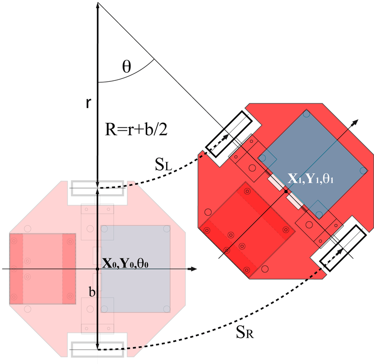
The next diagram will explain how to deal with an Odometry in real time with a two wheeled robot using quadrature encoders.
The next code explaining how to implement Odometry in real time in an arduino.
In this code I used a software interrupt of 120ms (toooo much) get more assured that arduino is not for real time application
l=0.5*(positionRight+positionLeft); Theta=positionRight-positionLeft; vitesse=l-lastL; lastL=l; Theta%=2292; //2292 is the number that corresponds to 2*pi double Theta_r=(double)Theta*0.002734;//Theta in radian deltaX=-vitesse*sin(Theta_r); deltaY=vitesse*cos(Theta_r); x+=deltaX; y+=deltaY;
Posted by
Unknown
at
2:12 PMon Saturday, October 13, 2012
Have you ever wanted to do the same thing at the same time to win more time?! Cleaning the house while doing your homework :D that would be very helpful. Working with embedded systems made crucial to deal with different tasks at the same time while having (most of the time) only one CPU that can handle only one task at a time. To schedule between different tasks, embedded systems use RTOS (real time operating systems) which is in same how a little software is responsible to manage all the different tasks that want to use the CPU.
I found lately a wonderful tool to programme STM32 microcontrollers which is CoIDE from Coocox. It's based on the eclipse which makes programming the STM32 a lovely journey you don't want to miss. You can download Cocenter from here which contains all the other great software that come with CoIDE like CoOS which is a free RTOS that we will use it in this Tutorial.
So... Our mission is to blink a led in an infinite task and to watch for the value of the button in an other task. I used the STM32 discovery board that contains an STM32F100RB.
After creating a project in your CoIDE, make sure to add the GPIO, RCC and CoOS libraries from the repository.