on Friday, June 1, 2012
So here I am founding my self learning the NXT lego mindstorm kit for robotics to teach some robotic lessons to some kids with my friend Helmi.

I didn't play with lego when I was young and I didn't make any robot neither but I found that learning such things in early age is just great cause robotics include many disciplines like mathematics physics algorithms mechanics and even chemistry in some cases so for a child this is a great opportunity to boost his way of thinking perception searching for information and finding solutions without mentioning increasing his self confidence and sense of innovation and creation with such a simple tool simple tasks but with amazing results.
Sure I will post some of NXT robotics experience. Till that day keep sharing :)

on Tuesday, May 15, 2012

Meet,


Mr Proportional
a fat guy that eat too much his one and only issue is his stomach :pp


Mr Integrator

 a punctual guy and obsessed with time he can never be satisfied with something unless he finished it all.


Mr Derivator
an athlete that loves to run, sometimes slow and sometimes fast and he can make his colleagues run faster.


Mr P Mr I and Mr D can make a great combination to make any system work at his best withe all the energy that given by Mr P all the punctuality that is given by Mr I and all the speed that it's given by Mr D.


So PID Controller is a command law that controls a system to respond to a specific order.
Our objective to make a specific system respond to our command with the minimum possible error as fast as possible and with maintaining it's stabilité

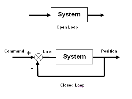
So let's look to this system:
It can be controlled by two different way.
The first method is an open loop command  it's a very simple command we just put the command manually and the system will react according to that command BUT that means we don't have any idea about what's going on in the end and even that we can observe our system working we don't have an exact idea about his performance.

The second method is a close loop command that means we give a desired goal for example a specific position the system then will calculate the error = desired goal - output and create the command accordingly so in this case the command is generated automatically. 
here we can notice that the desired goal and the output must be with the same unity that means the desired goal must much the unity of the system output.

Where's the PID?

well PID regulator is the first one which meets the error calculated each time.


As we already saw Mr P, I and D are the 3 gentlemen who constitute the PID regulator.

Mr P is simply the error that we already talked about.
Mr I is the sum of all the errors calculated
Mr D present the Dynamic of the errors whether the error value are changed suddenly or smoothly we should consider that in out regulator.

How can I much this gentlemen with my specific system?

well here we need a little magic. You should know the exact amount of food to give to Mr P Let's called Kp. The exact sense of punctuality to Mr I (Ki) and the perfect body to Mr D (Kd).

Implementation:

If you want to implement your PID controller into a microcontroller you need to follow this steps;

1° Create a Timer interrupt (which represent the sampling time)
2° predefine your PID parameters
3° in the Timer routine calculate the 3 Mrs:
   MrP = target-output
-------------------------------
  MrI=MrP+LastMrI
 LastMr+=MrI
------------------------------
MrD=MrP-LastMrD
LastMrD=MrP
------------------------------
4°calculate the correction
 correction = Kp*Mrp+Ki*MrI+ Kd*MrD
5°Saturation:
correction mustn't exceed the maximum value the actuator would take so we need to do a saturation routine

N°: Sometimes "correction" have negative values so if we are dealing with motors that means turning in the other sens if we are dealing with a temperature regulation that means we should stop or cooling our system.
on Sunday, May 6, 2012
visual assistant is a wonderful tool that allows you to create complex image processing alghorithm with simple cliks

In this tutorial I'm using a PIC18F4550 with 48MHz crystal to communicate through usb with PC.
If you are using proteus ISIS I'm happy to tell you that there's a wonderful feature which create a virtual usb driver so you don't need any electronics to test your program.

I'm going to show you how to create a project that includes the usb HID (Human interface devices) library. So after this project you will be able to create your own HID devices with your product and vendor IDs.

First start by creating a new Projects with all the settings mentioned above and copy this code which is by the way the example code given by the Help.

unsigned char readbuff[64] absolute 0x500;   // Buffers should be in USB RAM, please consult datasheet
unsigned char writebuff[64] absolute 0x540;

char cnt;
char kk;

void interrupt(){
   USB_Interrupt_Proc();                   // USB servicing is done inside the interrupt
}

void main(void){
  ADCON1 |= 0x0F;                         // Configure all ports with analog function as digital
  CMCON  |= 7;                            // Disable comparators

  HID_Enable(&readbuff,&writebuff);       // Enable HID communication

  while(1){
    while(!HID_Read())
      ;

    for(cnt=0;cnt<64;cnt++)
      writebuff[cnt]=readbuff[cnt];

    while(!HID_Write(&writebuff,64))
      ;
  }
}
The code simply send back what he received ^^

Now Tools->HID terminal

Set your VID and PID your Vendor Name and Product Name as you want.
Then select the mikroC radio and save your descriptor file with your project files (not an obligation but recommended :p ).

Go to view-->project manager
right click on the "source" folder and choose "add files to project" to add the descriptor file you already created.

before compiling one last step:
go to edit project and set it like in the picture


Finally Compile your project. It should work fine if you are not using the demo version.


on Wednesday, March 28, 2012
Hi,
I was working the last days on a project of gesture recognition using labview.
Labview is a great program, a simple programmer can easily learn the graphical language it use, because everything in labview is referred as block and the relations between blocks are maintained with wires.
In my projects I used the vision toolkit which is one of the most great toolKit in labview. Now I can control numerique or analogic data only through my hand.

This is an update:
I continued the project with two of my freinds helmi and slim, we can now control actuator with gestur recognition we succeded at controling the speed of a dc motor by just moving our fingurs :))


It was a great experience :)


on Monday, February 27, 2012

PIC has a lot of interesting features and one of them is the amazing portb that can create hardware interruption in each variation.

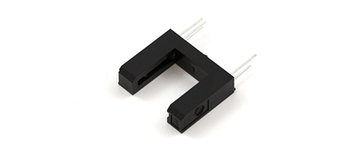
the code above I used to read data from an optical fork.

The code is very simple:

every time there is a state change in one of the portb pin we enter the interrupt routine and we can do whatever we want to do there.

I used the timer 0 interruption just in case you want to do know the number of hardware interruption each period of time.

I used PIC18F4550 and 40Mhz oscillator.

int read=0;
int left=0;
int right=0;
int l =0;
int riL =0;
char txt[7];
void interrupt(){
if(TMR2IF_bit){
portd.RD4=~portd.RD4;
left=l;
l=0;
TMR2IF_bit=0;//never forget to put 0 int the flag after interruption
}
if(INTCON.RBIF==1){
portd.RD2=~portd.RD2;
l++;
read=portb;
INTCON.RBIF=0;
}
}
void init(){
portd=0X00;
trisd=0X00;
portb=0X00;
trisb=0XFF;
//initialisation de ports
intcon=0XC8;
//initialisation des interruption global(GIE,PIE,RBE)
t2con=0X07;
TMR2IE_bit=1;
//timer 2
uart1_init(9600);
}
void main() {
init();
while(1){
inttostr(left,txt);
uart1_write_text(txt);
uart1_write(10);
uart1_write(13);//pour la visualisation

};


}

on Tuesday, February 14, 2012


Hello, 
I've already tested openCV and found a little difficulties to integrate it in a windows form application, although openCV is a great library it's still lack of this characteristic, well I found another magnificent library not so powerful as openCV but can be easily integrated in a c#.net application, it's Aforge.net

It's much easier to learn this framework if you already have knowledge of image processing.
..So I create this application that reads the images from a cheap web cam and look for a specific color in the image get some values from it(x,y,widht) to control a servo via an arduino mega ADK.

To find the object I used blob detection after filter the image with HSLfilter and the convert it to gray scale so I can use the blob detection algorithm  which works only with Binary or gray images.

after that I send the X values of the object through serial to an arduino, where I map it to control a servo angle.

c# code:
using System;
using System.Collections.Generic;
using System.ComponentModel;
using System.Data;
using System.Drawing;
using System.Linq;
using System.Text;
using System.Windows.Forms;
using AForge;
using AForge.Video;
using AForge.Video.DirectShow;
using AForge.Imaging.Filters;
using AForge.Imaging;

namespace hslfilterblob
{
    public partial class Form1 : Form
    {
        private FilterInfoCollection videoCaptureDevices;
        private VideoCaptureDevice finalVideo;
        private int minHue = 0, maxHue = 355;
        private float minLum = 0, maxLum = 1, minSat = 0, maxSat = 1;
        private Byte[] buffer = new Byte[1];
        private bool serialok = false;
        private float map = 0f;

        public Form1()
        {
            InitializeComponent();
            videoCaptureDevices = new FilterInfoCollection(FilterCategory.VideoInputDevice);
            finalVideo = new VideoCaptureDevice(videoCaptureDevices[1].MonikerString);
            finalVideo.NewFrame += new NewFrameEventHandler(Finalvideo_newframe);
            finalVideo.Start();
        }

        void Finalvideo_newframe(object sender, NewFrameEventArgs eventArgs)
        {
            Bitmap video = (Bitmap)eventArgs.Frame.Clone();
            Bitmap video2 = (Bitmap)eventArgs.Frame.Clone();
            //Create color filter
            HSLFiltering HslFilter = new HSLFiltering();
            //configre the filter
            HslFilter.Hue = new AForge.IntRange(minHue, maxHue);
            HslFilter.Saturation = new AForge.Range(minSat, maxSat);
            HslFilter.Luminance = new AForge.Range(minLum, maxLum);
            //apply color filter to the image
            HslFilter.ApplyInPlace(video2);
            //create gray filter
            Grayscale grayFilter = new GrayscaleBT709();
            Bitmap grayImage = grayFilter.Apply(video2);
            //display Image
            BlobCounter blobcounter = new BlobCounter();
            blobcounter.MinHeight = 100;
            blobcounter.MinWidth = 100;
            blobcounter.ObjectsOrder = ObjectsOrder.Size;
            //locate blobs
            blobcounter.ProcessImage(grayImage);
            Rectangle[] rects = blobcounter.GetObjectsRectangles();
            //draw rectangle around the biggest blob
            if (rects.Length > 0)
            {
                Rectangle objectRect1 = rects[0];
              
                Graphics g = Graphics.FromImage(video);

                    using (Pen pen = new Pen(Color.Red, 3))
                    {
                        g.DrawRectangle(pen, objectRect1);
                        PointF drawPoin = new PointF(objectRect1.X,objectRect1.Y);
                        int objectX = objectRect1.X + objectRect1.Width / 2 - video.Width / 2;
                        int objectY = video.Height / 2 - (objectRect1.Y + objectRect1.Height / 2);
                        String Blobinformation = "X= "+objectX.ToString()+"\nY= "+objectY.ToString()+"\nSize="+objectRect1.Size.ToString();
                        g.DrawString(Blobinformation, new Font("Arial", 16), new SolidBrush(Color.Blue), drawPoin);
                       
                        if (serialok == true)
                        {
                            int second =0;
                            int offset=300;
                            second = offset - Math.Abs(objectX);
                            map =(float) 0.85 * second;
                            buffer[0] = (byte)Math.Abs((int)map);
                            serialPort1.Write(buffer, 0, 1);
                        }
                    }
                    g.Dispose();
               
            }          
            pictureBox1.Image = video;
            pictureBox2.Image = grayImage;
        }

        private void trackBarMaxHue_Scroll(object sender, EventArgs e)
        {
            maxHue = trackBarMaxHue.Value;
        }

        private void trackBarMinHue_Scroll(object sender, EventArgs e)
        {
            minHue = trackBarMinHue.Value;
        }

        private void trackBarMaxSat_Scroll(object sender, EventArgs e)
        {
            maxSat = trackBarMaxSat.Value / 100F;
        }

        private void trackBarSatMin_Scroll(object sender, EventArgs e)
        {
            minSat = trackBarSatMin.Value / 100F;
        }

        private void trackBarLumMax_Scroll(object sender, EventArgs e)
        {
            maxLum = trackBarLumMax.Value / 100F;
        }

        private void trackBarLumMin_Scroll(object sender, EventArgs e)
        {
            minLum = trackBarSatMin.Value / 100F;
        }

        private void button1_Click(object sender, EventArgs e)
        {
            ColorDialog colorDlg = new ColorDialog();
            colorDlg.AnyColor = true;
            colorDlg.SolidColorOnly = false;
            colorDlg.Color = Color.Red;

            if (colorDlg.ShowDialog() == DialogResult.OK)
            {
                textBox1.Text = colorDlg.Color.GetHue().ToString();
                textBox2.Text = colorDlg.Color.GetSaturation().ToString();
                textBox3.Text = colorDlg.Color.GetBrightness().ToString();
            }
        }

        private void btnCommunication_Click(object sender, EventArgs e)
        {
            try
            {
                serialPort1.Open();
                btnCommunication.BackColor = Color.Green;
                serialok = true;
            }
            catch (Exception t)
            {
                MessageBox.Show(t.ToString());
            }
        }
    }
}

arduino code:

#include <Servo.h>

Servo servo1;
int inbyte=0;
int i;
void setup(){
  servo1.attach(2);
  Serial.begin(9600);
  Serial.println("Start!");
 
  for(i=0;i<180;i++){
    servo1.write(i);
    delay(15);
  }
  servo1.write(90);
}

void loop(){
  if(Serial.available()>0){
    inbyte=Serial.read();
       
  }
     servo1.write(map(inbyte,0,255,0,180));
     delay(15);
}