on Sunday, February 17, 2013
So what's wrong with Tunisia!! with such great talents spread all over the world with such an honorable history with such immense agriculture potential Tunisia falls in its greatness.
So many talents so many good minds so many charismatic people and so many diversity but it seems that all of this positive line qualities Tunisia doesn't seems to get use of it, but instead this diversity this democracy is just dividing us more and more.
About 12 million person are living now in Tunisia, but even with this relatively small number of population we have more than 200 categories of Tunisian people, salfi, nahthawi, cpr, pdp, joumhouri, masar, ili m3a te2sisii willi mouch m3ehom welli me3inouch bech itabe3,.....
It seems that our diversity is playing against us. It seems that our qualities is our enemies.
It seems that democracy is not the solution.
on Friday, February 8, 2013


The need of static power supply

The need of power voltage supply is mandatory in any mechatronic application. For mobile mechatronic applications like robots, the power voltage supplier must be embedded with the application this can deliver many drawback like for example autonomy.
But when dealing with static mechatronic projects we can just get rid of the battery and use directly the domestic AC power supplier. because this supplier can deliver energy 24/7 with one drawback that this energy must be calibrated to be used in static mechatronic application witch are usually need a DC supply voltage.
In this article I'm going to show you how to create you own DC power supply.

Specifications 

INPUT : 220 V AC
OUTPUT: 5V DC / 1.5A

Principal functions:

 Our board change the 220V AC into 5V DC with a maximum operating current of 1.5A

Current protection : 


we need to protect the board from unpredictable current variation from the power supply or potential shunt that could be very dangerous and can harm our system. The obvious solution is to use a fuse.
The maximum needed current for mini mechatronic applications is 1A with a tolerance of 500mA so any current that exceeds 1.5A would be considered as dangerous to the board and the fuse must interfere. The choice is then a fuse with a normal operating current = 1.5A.


Galvanic isolation and Voltage decreasing

This part of the board is mainly responsible for decreasing the alternative voltage from 220V to 12V alternative current.
For this purpose we need a 220v 12V transformer that can assure both of the functions

Wave rectification


This part of the board is probably the most important, In fact in this part the alternative energy is transformed to a direct one. we need to eliminate the negative part of the wave or replace it with a positive wave.
For this purpose we need a full wave rectifier composed by 4 1N4001 Diodes:

Filtering and smoothing

The rectified wave still need to be more smoothed so I have to fill the gaps between the waves. To do so we need to add a capacitor that able to store voltage and release it in time to fill the gaps.
The specifications needed for our board are :
Vin :regulator input = 12V / Operating current = 1A
C = I * detlta(T)/delta(V) = 3333µF we take it as 4700µf or 2200µF

Voltage regulation

At this step we have a decent 12V DC but it's not really stable and we need to get the 5V DC To feed the electronics. For this purpose we have to add a 5V voltage regulator that can transform 12V to a stable 5v DC. The perfect choice is LM7805 witch is a 5V DC/DC regulator that is capable of supporting up to 1A witch is acceptable for the usual applications. It's recommended to add another filtering capacitor of 10mF in the output of the regulator to assure stabilization.


Integration of the hole design with Altium designer: 


on Saturday, November 17, 2012

When we are dealing with an autonomous mobile robot, the first thing comes to our mind is how this robot will locate it self while moving.

There are several methods to do that, But in this article I'm going to talk about Odometry ,or sometimes known by "Dead reckoning", for a two wheeled robot.

The main idea about Odometry is to use a foreknown distance unit in a cumulative way.
Let's get to this example, let's suppose that an adult step is about 1 meter. If this adult walks five steps then he walked 5 meters.
In an orthonormal reference (x,y) if this guy starts at (0,0) moves 5 steps in the direction of Y then he's new position is updated and it's (0,5).
If later he moves 5 steps in the direction of X he new position will be updated compared to he's last position so he's new position is  (5,5).
Let's suppose that the adult turn him self while walking and instead of walking 5 steps towards Y then 5 towards X.
He starts with an angel Theta =45° and goes 7 steps ( Distance=~ sqrt(50))
In this case we can tell his X and Y position with simple trigonometry.

X=Distance*Cos(Theta) =~ 5
Y= Distance*Sin(Theta) =~ 5
(X,Y) = (5,5)


Back to robotics Now :p
If we suppose that these guy is a two wheeled robot the measurement of the foreknown distance would be extracted from sensors like quadrature encoders IMU or something else.

We need to know the position of the robot in real time, that means every small sampling time (10 ms is good) we need to recalculate the distance the robot traveled and the angel it did to calculate it's new position. After that we add this position to last calculated position and so on. just like we did with the guy.

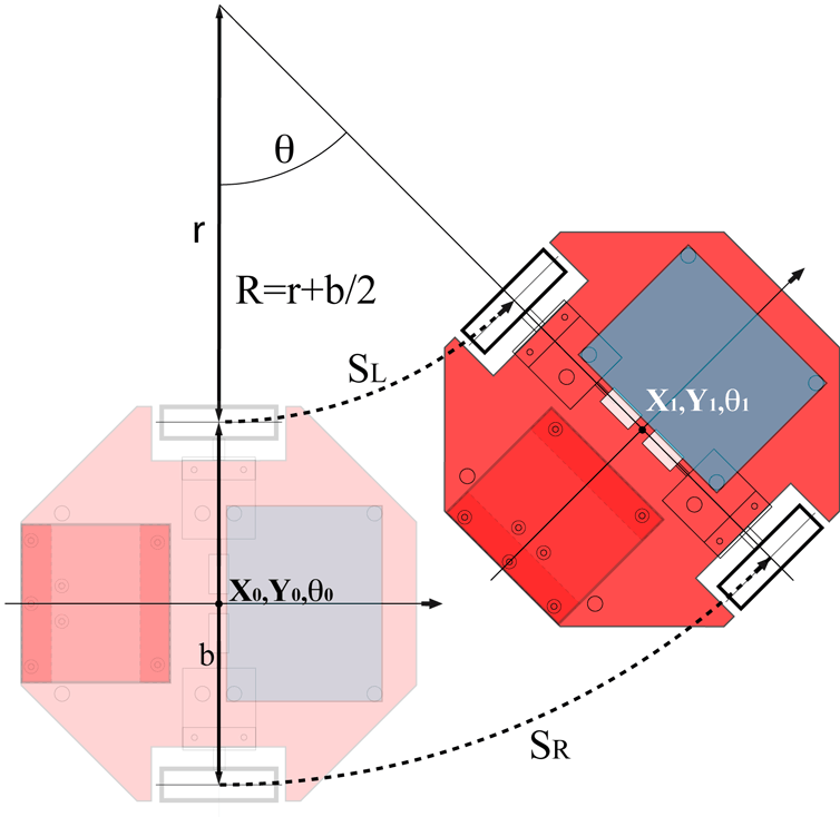
The next diagram will explain how to deal with an Odometry in real time with a two wheeled robot using quadrature encoders.

The next code explaining how to implement Odometry in real time in an arduino.
In this code I used a software interrupt of 120ms (toooo much) get more assured that arduino is not for real time application

  l=0.5*(positionRight+positionLeft);
  Theta=positionRight-positionLeft;
  vitesse=l-lastL;
  lastL=l;
  Theta%=2292; //2292 is the number that corresponds to 2*pi
  double Theta_r=(double)Theta*0.002734;//Theta in radian
  deltaX=-vitesse*sin(Theta_r);
  deltaY=vitesse*cos(Theta_r);
  x+=deltaX;
  y+=deltaY;


Cheers :)


on Saturday, October 13, 2012
Have you ever wanted to do the same thing at the same time to win more time?! Cleaning the house while doing your homework :D that would be very helpful.
Working with embedded systems made crucial to deal with different tasks at the same time while having (most of the time) only one CPU that can handle only one task at a time.
To schedule between different tasks, embedded systems use RTOS (real time operating systems) which is in same how a little software is responsible to manage all the different tasks that want to use the CPU.

I found lately a wonderful tool to programme STM32 microcontrollers which is CoIDE from Coocox. It's based on the eclipse which makes programming the STM32 a lovely journey you don't want to miss.
 You can download Cocenter from here which contains all the other great software that come with CoIDE like CoOS which is a free RTOS that we will use it in this Tutorial.


So... Our mission is to blink a led in an infinite task and to watch for the value of the button in an other task.
I used the STM32 discovery board that contains an STM32F100RB.


After creating a project in your CoIDE, make sure to add the GPIO, RCC and CoOS libraries from the repository.

#include "stm32f10x.h"
#include "stm32f10x_gpio.h"
#include "stm32f10x_rcc.h"
#include <CoOs.h>

#define STACK_SIZE_DEFAULT 512

OS_STK task1_stk[STACK_SIZE_DEFAULT];
OS_STK task2_stk[STACK_SIZE_DEFAULT];

void initializeBoard(){

        GPIO_InitTypeDef GPIO_InitStructure_Led;
        GPIO_InitTypeDef GPIO_InitStructure_Button;

        RCC_APB2PeriphClockCmd(RCC_APB2Periph_GPIOC,ENABLE);//for LEds
        RCC_APB2PeriphClockCmd(RCC_APB2Periph_GPIOA,ENABLE);//for buttons

        GPIO_InitStructure_Led.GPIO_Pin = GPIO_Pin_8 | GPIO_Pin_9;
        GPIO_InitStructure_Led.GPIO_Mode = GPIO_Mode_Out_PP;
        GPIO_InitStructure_Led.GPIO_Speed = GPIO_Speed_50MHz;

        GPIO_InitStructure_Button.GPIO_Pin = GPIO_Pin_0;
        GPIO_InitStructure_Button.GPIO_Mode = GPIO_Mode_IN_FLOATING;
        GPIO_InitStructure_Button.GPIO_Speed = GPIO_Speed_50MHz;

        GPIO_Init(GPIOC,&GPIO_InitStructure_Led);
        GPIO_Init(GPIOA,&GPIO_InitStructure_Button);

}

void task1 (void* pdata){
        while(1){
                GPIO_WriteBit(GPIOC,GPIO_Pin_8,Bit_SET);
                CoTickDelay (10);
                GPIO_WriteBit(GPIOC,GPIO_Pin_8,Bit_RESET);
                CoTickDelay (10);
        }
}

void task2 (void* pdata){
        int i;
        while(1){
                i = GPIO_ReadInputDataBit(GPIOA,GPIO_Pin_0);
                GPIO_WriteBit(GPIOC,GPIO_Pin_9,i);
        }
}

int main(void)
{
        initializeBoard();
        CoInitOS();
        CoCreateTask(task1,0,0,&task1_stk[STACK_SIZE_DEFAULT-1],STACK_SIZE_DEFAULT);
        CoCreateTask(task2,0,1,&task2_stk[STACK_SIZE_DEFAULT-1],STACK_SIZE_DEFAULT);
        CoStartOS();
    while(1);
}


on Tuesday, September 25, 2012
on Friday, August 24, 2012


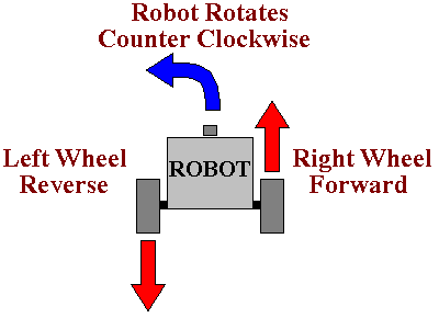
In this class we learned the final type of rotations : the point rotation
We need this kind of rotation when the robot must change its angle without changing its position in other words the robot rotate itself.
To make a robot turn a point rotation the wheels must rotate with the same speed but with different directions
This kind of rotation is very helpful in sharp angles <30°
To illustrate this kind of rotation we made a circuit which look like the heart beat:
The center of the robot must follow the circuit with no tolerance.

To apply a point rotation with the nxt-g just drag the steering to the extreme right or left then set the desired duration.


The second type of rotation that we will handle is parallel rotation:

This is the most common way of rotation for four wheels vehicles like cars.
The main idea is to turn the two wheels with different speed, so for a period of time the distance traveled by the faster wheel is more than the slower wheel as a result we don’t have straight movement but curve movement.
To apply this kind of rotation in a bidirectional robot like we have we used this circuit.

The circuit is very similar to a circle.
Ls will try to apply the swing rotation in this circuit but they will find it very painful, the great surprise I had that ls find by themselves the solution which lays in the Steering parameter we already see in the move block which is responsible for turning a bidirectional robot like a bicycle (well this is the example I used may be you will find better examples :=))

You can try other circuit like a snake body circuit for example.