on Wednesday, October 9, 2013
We really need to integrate ourselves in the middle of social life, a person that cannot integrate in his society would be qualified as non normal or with no regular behavior.
The fact is, that integrating in the society is a very relative concept, a person that cannot integrate himself in a specific society could be the most popular in another society, and we take the example of gamers or real geeks that bunch of guys that are so addicted to a video game or hacking computer software, have real problem with integrating within a society where the one who can use MSWord is qualified as a one who masters the computer. But the same Geeky person would be so popular in a society of geeks.

Here we go back to the point that in order to be popular or at least can integrate in a society, a person MUST share with the society its common believes, practices, way of thinking and looking to the world.
To integrate with a society a person must talk like they talk even if there is actually nothing wrong with hes talking and way of reasoning, a person must joke like they do, eat like they do even if it'is not healthy for him to eat the food they eat or the way they eat not eating like them take a -1 from his popularity mark.

The problem is not integrating could be very harmful for some people, the fact that they loose connection with their entourage and surrounding colleagues, the fact that they are not respected or acknowledged for what they do best. For example a person who masters fishing would have no value in a society of hunters. And here we conclude that to integrate in a society, you must actual do something that is relevant and useful for them, otherwise a person with deviated skills cannot easily integrate with a society.

But any person in the world no matter how intelligent, crazy, ugly, beautiful, rich or poor need to have people surrounding him, that can talk with him ask for him and worry about him. It is a natural need and it's very harmful to take it from someone which hes only curse that he was born with a deviated skills.

So any person in this world must be conscious of this fact, and therefore open his mind to different ideas and different believes. respect the other competence even if it is not relevant to him it could be relevant for someone else, it could help other societies.
Any person should not judge other people way of thinking as bizarre or weird, he could actual look more bizarre in another Time and Place Circumstances.

Finally, I would like to invite you to be more opened with weird people, they are actually more interesting than the typical believes.

Mazen


on Friday, September 20, 2013
LCD can be a very useful part in any microcontroller based project. It helps to monitor variables and program status with simple texts or numbers.

For this application I used a JHD 162 A alphanumeric LCD, like the picture above.
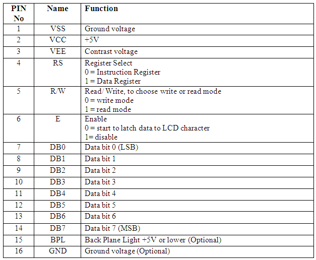
It hast 16 pins specified like this
VEE is used for contrast, so attache it to a potentiometer  and choose your best contrast. Or simply plug it to 5V if you need maximum contrast.
D0, D1, D2, D3 are grounded
I managed to find a library for STM32VL, so I needed to bring some changes to it before it works. This library works both for JHD 162A and the hd44780.

lcd_hd44780.h
//******************************************************************************
// THE SOFTWARE INCLUDED IN THIS FILE IS FOR GUIDANCE ONLY.
// AUTHOR SHALL NOT BE HELD LIABLE FOR ANY DIRECT, INDIRECT
// OR CONSEQUENTIAL DAMAGES WITH RESPECT TO ANY CLAIMS ARISING
// FROM USE OF THIS SOFTWARE.
//******************************************************************************

//##############################################################################
// lcd_hd44780.h
//##############################################################################

//****************************************************************************//
#include "main.h"


#define LCD_GPIO GPIOD
#define LCD_CLK_LINE RCC_AHB1Periph_GPIOD

#define LCD_D4 GPIO_Pin_1
#define LCD_D5 GPIO_Pin_3
#define LCD_D6 GPIO_Pin_5
#define LCD_D7 GPIO_Pin_7

#define LCD_RS GPIO_Pin_0
#define LCD_RW GPIO_Pin_2
#define LCD_EN GPIO_Pin_4
//******************************************************************************//


#define HD44780_CLEAR 0x01

#define HD44780_HOME 0x02

#define HD44780_ENTRY_MODE 0x04
#define HD44780_EM_SHIFT_CURSOR 0
#define HD44780_EM_SHIFT_DISPLAY 1
#define HD44780_EM_DECREMENT 0
#define HD44780_EM_INCREMENT 2

#define HD44780_DISPLAY_ONOFF 0x08
#define HD44780_DISPLAY_OFF 0
#define HD44780_DISPLAY_ON 4
#define HD44780_CURSOR_OFF 0
#define HD44780_CURSOR_ON 2
#define HD44780_CURSOR_NOBLINK 0
#define HD44780_CURSOR_BLINK 1

#define HD44780_DISPLAY_CURSOR_SHIFT 0x10
#define HD44780_SHIFT_CURSOR 0
#define HD44780_SHIFT_DISPLAY 8
#define HD44780_SHIFT_LEFT 0
#define HD44780_SHIFT_RIGHT 4

#define HD44780_FUNCTION_SET 0x20
#define HD44780_FONT5x7 0
#define HD44780_FONT5x10 4
#define HD44780_ONE_LINE 0
#define HD44780_TWO_LINE 8
#define HD44780_4_BIT 0
#define HD44780_8_BIT 16

#define HD44780_CGRAM_SET 0x40

#define HD44780_DDRAM_SET 0x80

//##############################################################
void lcd_init(void);
void lcd_cls(void);
void lcd_str(unsigned char * text);
void lcd_strxy(unsigned char * text, unsigned char x, unsigned char y);
void lcd_locate(unsigned char x, unsigned char y);
void lcd_int(int n);
void lcd_intxy(int n, unsigned char x, unsigned char y);

//###############################################################

void lcd_writedata(unsigned char dataToWrite);
void lcd_writecommand(unsigned char commandToWrite);
void lcd_writebinary(unsigned int var, unsigned char bitCount);
void lcd_addchar (unsigned char chrNum, unsigned char n, const unsigned char *p);


lcd_hd44780.c
#include "lcd_hd44780.h"
#include "stm32f4xx_gpio.h"
#include
#include
#include
#include "stm32f4_discovery.h"

GPIO_InitTypeDef GPIO_InitStructure;

//-----------------------------------------------------------------------------
void lcd_writenibble(unsigned char nibbleToWrite)
{
GPIO_WriteBit(LCD_GPIO, LCD_EN, Bit_SET);
GPIO_WriteBit(LCD_GPIO, LCD_D4,(BitAction) (nibbleToWrite & 0x01));
GPIO_WriteBit(LCD_GPIO, LCD_D5,(BitAction)(nibbleToWrite & 0x02));
GPIO_WriteBit(LCD_GPIO, LCD_D6,(BitAction)(nibbleToWrite & 0x04));
GPIO_WriteBit(LCD_GPIO, LCD_D7,(BitAction)(nibbleToWrite & 0x08));
GPIO_WriteBit(LCD_GPIO, LCD_EN, Bit_RESET);
}


//-----------------------------------------------------------------------------
unsigned char LCD_ReadNibble(void)
{
unsigned char tmp = 0;
GPIO_WriteBit(LCD_GPIO, LCD_EN, Bit_SET);
tmp |= (GPIO_ReadInputDataBit(LCD_GPIO, LCD_D4) << 0);
tmp |= (GPIO_ReadInputDataBit(LCD_GPIO, LCD_D5) << 1);
tmp |= (GPIO_ReadInputDataBit(LCD_GPIO, LCD_D6) << 2);
tmp |= (GPIO_ReadInputDataBit(LCD_GPIO, LCD_D7) << 3);
GPIO_WriteBit(LCD_GPIO, LCD_EN, Bit_RESET);
return tmp;
}


//-----------------------------------------------------------------------------
unsigned char LCD_ReadStatus(void)
{
unsigned char status = 0;

GPIO_InitStructure.GPIO_Pin = LCD_D4 | LCD_D5 | LCD_D6 | LCD_D7;
GPIO_InitStructure.GPIO_Mode = GPIO_Mode_IN;
GPIO_Init(LCD_GPIO, &GPIO_InitStructure);

GPIO_WriteBit(LCD_GPIO, LCD_RW, Bit_SET);
GPIO_WriteBit(LCD_GPIO, LCD_RS, Bit_RESET);

status |= (LCD_ReadNibble() << 4);
status |= LCD_ReadNibble();

GPIO_InitStructure.GPIO_Pin = LCD_D4 | LCD_D5 | LCD_D6 | LCD_D7;
GPIO_InitStructure.GPIO_Mode = GPIO_Mode_OUT;
GPIO_Init(LCD_GPIO, &GPIO_InitStructure);

return status;
}


//-----------------------------------------------------------------------------
void lcd_writedata(unsigned char dataToWrite)
{
GPIO_WriteBit(LCD_GPIO, LCD_RW, Bit_RESET);
GPIO_WriteBit(LCD_GPIO, LCD_RS, Bit_SET);

lcd_writenibble(dataToWrite >> 4);
lcd_writenibble(dataToWrite & 0x0F);

while(LCD_ReadStatus() & 0x80);
}


//-----------------------------------------------------------------------------
void lcd_writecommand(unsigned char commandToWrite)
{
GPIO_WriteBit(LCD_GPIO, LCD_RW | LCD_RS, Bit_RESET);
lcd_writenibble(commandToWrite >> 4);
lcd_writenibble(commandToWrite & 0x0F);

while(LCD_ReadStatus() & 0x80);
}


//-----------------------------------------------------------------------------
void lcd_str(unsigned char * text)
{
while(*text)
lcd_writedata(*text++);
}


//-----------------------------------------------------------------------------
void lcd_locate(unsigned char x, unsigned char y)
{
lcd_writecommand(HD44780_DDRAM_SET | (x + (0x40 * y)));
}


//-----------------------------------------------------------------------------
void lcd_strxy(unsigned char * text, unsigned char x, unsigned char y)
{
lcd_locate(x,y);
while(*text)
lcd_writedata(*text++);
}


//-----------------------------------------------------------------------------
void lcd_writebinary(unsigned int var, unsigned char bitCount)
{
signed char i;

for(i = (bitCount - 1); i >= 0; i--)
{
lcd_writedata((var & (1 << i))?'1':'0');
}
}


//-----------------------------------------------------------------------------
void LCD_ShiftLeft(void)
{
lcd_writecommand(HD44780_DISPLAY_CURSOR_SHIFT | HD44780_SHIFT_LEFT | HD44780_SHIFT_DISPLAY);
}


//-----------------------------------------------------------------------------
void LCD_ShiftRight(void)
{
lcd_writecommand(HD44780_DISPLAY_CURSOR_SHIFT | HD44780_SHIFT_RIGHT | HD44780_SHIFT_DISPLAY);
}


//-----------------------------------------------------------------------------
void lcd_init(void)
{
volatile unsigned char i = 0;
volatile unsigned int delayCnt = 0;
RCC_AHB1PeriphClockCmd(LCD_CLK_LINE, ENABLE);
GPIO_InitStructure.GPIO_Pin = LCD_D4|LCD_D5|LCD_D6|LCD_D7|LCD_RS|LCD_RW|LCD_EN;
GPIO_InitStructure.GPIO_Speed = GPIO_Speed_50MHz;
GPIO_InitStructure.GPIO_Mode = GPIO_Mode_OUT;

GPIO_Init(LCD_GPIO, &GPIO_InitStructure);

GPIO_ResetBits(LCD_GPIO, LCD_RS | LCD_EN | LCD_RW);

for(delayCnt = 0; delayCnt < 300000; delayCnt++);

for(i = 0; i < 3; i++) {
lcd_writenibble(0x03);
for(delayCnt = 0; delayCnt < 30000; delayCnt++);
}

lcd_writenibble(0x02);

for(delayCnt = 0; delayCnt < 6000; delayCnt++);

lcd_writecommand(HD44780_FUNCTION_SET |
HD44780_FONT5x7 |
HD44780_TWO_LINE |
HD44780_4_BIT);

lcd_writecommand(HD44780_DISPLAY_ONOFF |
HD44780_DISPLAY_OFF);

lcd_writecommand(HD44780_CLEAR);

lcd_writecommand(HD44780_ENTRY_MODE |
HD44780_EM_SHIFT_CURSOR |
HD44780_EM_INCREMENT);

lcd_writecommand(HD44780_DISPLAY_ONOFF |
HD44780_DISPLAY_ON |
HD44780_CURSOR_OFF |
HD44780_CURSOR_NOBLINK);

}


//-----------------------------------------------------------------------------
void lcd_addchar (unsigned char chrNum, unsigned char n, const unsigned char *p)
{
lcd_writecommand(HD44780_CGRAM_SET | chrNum * 8);
n *= 8;
do
lcd_writedata(*p++);
while (--n);
}


//-----------------------------------------------------------------------------
void lcd_cls(void){
lcd_writecommand(HD44780_CLEAR);
}


unsigned char* intToStr(int n){
int i = 0;
int j = 0;
char *tmp = (char*)malloc(sizeof(char));
unsigned char *ret = (unsigned char*)malloc(12);
if(n<0 data-blogger-escaped-i="" data-blogger-escaped-j="" data-blogger-escaped-n="" data-blogger-escaped-ret="-" data-blogger-escaped-while="">9){
*tmp = n%10+48;
n-=n%10;
n/=10;
tmp++;
i++;
}
*tmp = n+48;
i++;
while(i--){
ret[j++] = *tmp--;
}
return ret;
}
void lcd_int(int a){
unsigned short ch,
first; //you need this to display 0 if there was any char

//Get first char
ch = a/10000;
if(ch){
lcd_writedata(48+ch);
first = 1;
}

//Get second char
ch = (a/1000)%10;
if(ch || first){
lcd_writedata(48+ch);
first = 1;
}

//Get third char
ch = (a/100)%10;
if(ch || first){
lcd_writedata(48+ch);
first = 1;
}

//Get fourth char
ch = (a/10)%10;
if(ch || first){
lcd_writedata(48+ch);
//first = 1; //q
}

//Get fifth char
ch = a%10;
//if(ch || first) //you dont need to check las one if ch is 0 then just display it, unless you dont want to then uncomment this line ("//q" line too)
lcd_writedata(48+ch);
// lcd_str(intToStr(n));
}

void lcd_intxy(int n, unsigned char x, unsigned char y){
lcd_locate(x,y);
lcd_int(n);
}


main.c
lcd_init();

while (1)
{

lcd_locate(1,0);
lcd_str("Mazen");
lcd_locate(7,0);
lcd_str("A.");
lcd_locate(0,1);
lcd_str("-3125");

}

Update:
Number display function is fixed

on Monday, August 12, 2013
This is my first android application, it consists of something that I actually need during making electronic projects where there are so many resistors in the table and I can't just figure out the value of each one of them at a glance.
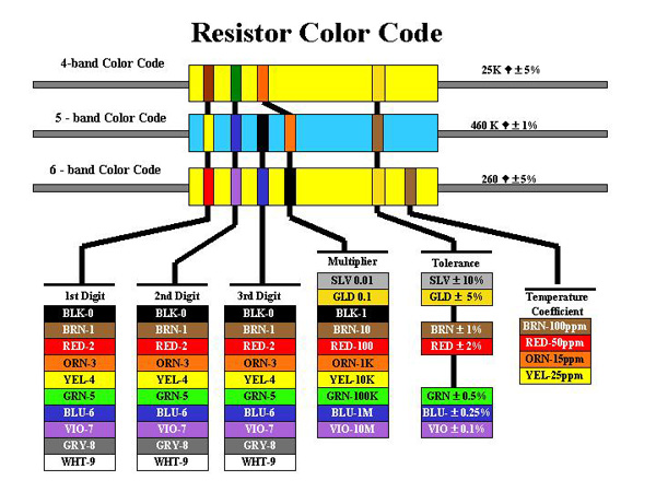
Resistors used code colors, and each color according to its position has a specific value.


A resistor can have 4, 5 or 6 color bands just like the following picture:

Each color rank have a specific meaning in each Resistor type. For example the third band (from the left) of a 4 band resistor is a multiplier digit, but in the 5 band resistor it is the unity digit.

The previous picture shows a resistor with 4 color bands, organized as follow (from left to right)
Brown, Black, Red, Gold
10*10^ 2 +/- 5%  = 1K ohm with 5% tolerance

For more information about how to calculate resistor color code, please refer to this wonderful wekipedia article:
http://fr.wikipedia.org/wiki/CEI_60757
I actually use this mnemonic in french "ne mange rien ou jeuner voila bien votre grande bétise" to remember the mean of each color in the resistance' but sometimes that could be very confusing, so I thought to create an android app that help with that.
I know that there is many android app doing that, but I did wanted to learn android too :D

The Android application:

In the Main activity, there are 3 buttons for each kind of resistor:
Each button open a new Activity through a simple intent in its OnClickListener() as follow:
btn4BandResistance.setOnClickListener(new OnClickListener() {

@Override
public void onClick(View v) {
Intent intent4 = new Intent(MainActivity.this,BandResistor4.class);
startActivity(intent4);
}
});
A new Activity opens, I used The Spinner View to choose from one of the predefined colors, and TextViews to show result:

I used a function that is called in each OnItemSelectedListener() of each spinner to update the results:
spin1Band4.setOnItemSelectedListener(new OnItemSelectedListener() {

@Override
public void onItemSelected(AdapterView arg0, View arg1,
int arg2, long arg3) {

update4BandResistance();
}

@Override
public void onNothingSelected(AdapterView arg0) {
// TODO Auto-generated method stub

}
});
the update function link the position of each selected Item to a value already defined in an Array:
 public void update4BandResistance(){
String unity;
TotalResistance = (ColorArrayBand[spin1Band4.getSelectedItemPosition()]+ColorArrayBand2[spin2Band4.getSelectedItemPosition()]) * ColorArrayMultiplier[spinMultiply4.getSelectedItemPosition()];
Tolerance = TotalResistance * ColorArrayTolerance[spin1Tolerance4.getSelectedItemPosition()];
if(TotalResistance>=1000000){
TotalResistance/=1000000;
unity = "M Ohm";
}
else if (TotalResistance>=1000){
TotalResistance /= 1000;
unity = "K Ohm";
}
else {
unity = "Ohm";
}
txtTolerance.setText(String.valueOf(TotalResistance + Tolerance)+"/"+String.valueOf(TotalResistance - Tolerance));
txtResistance.setText("R = "+String.valueOf(TotalResistance)+unity);
}

Finally I added some modification to the result for a more readable value:

The hole project can be found in github:
https://github.com/Mazen21/ResistanceCalculator

I'm looking forward for your suggestions:


on Monday, July 15, 2013
I've made some experiments using the STM32F3 discovery board, which is amazing by the way, and the mems(Micro ElectroMechnical Systems) in the board.


For more information about the board check this link where you will find all the technical hardware and software examples made with many IDEs.
The main idea of this article is to make a standalone IMU (Inertial Measurement Unit) using only the STM32F3 board, because it has all the necessary hardware for making a complete 9 DOF IMU.

To do so I need to read both of the Gyroscope and the accelerometer data collected in a way so I can send later to the PC using VCP (USB CDC).

I started with the VCP example for the STM32303c eval board, you can find here
And then I add both of stm32f3_discovery_lsm303dlhc.c and stm32f3_discovery_l3gd20.c, this two file could be found in the utitli folder of the firmware support for the STM32F3 board can be found here.

Then later I found this great files to give more abstract function to deal with the mems.

The complete project from here

Accelerometer.c
#ifndef _ACC_C_
#define _ACC_C_

#define LSM_Acc_Sensitivity_2g (float) 1.0f /*!< accelerometer sensitivity with 2 g full scale [LSB/mg] */
#define LSM_Acc_Sensitivity_4g (float) 0.5f /*!< accelerometer sensitivity with 4 g full scale [LSB/mg] */
#define LSM_Acc_Sensitivity_8g (float) 0.25f /*!< accelerometer sensitivity with 8 g full scale [LSB/mg] */
#define LSM_Acc_Sensitivity_16g (float) 0.0834f /*!< accelerometer sensitivity with 12 g full scale [LSB/mg] */

#include "Accelerometer.h"
#include "stm32f3_discovery_lsm303dlhc.h"
/**
* @brief Configure the Mems to Accelerometer MEMS.
* @param None
* @retval None
*/
void Acc_Config(void)
{
LSM303DLHCAcc_InitTypeDef LSM303DLHCAcc_InitStructure;
LSM303DLHCAcc_FilterConfigTypeDef LSM303DLHCFilter_InitStructure;

/* Fill the accelerometer structure */
LSM303DLHCAcc_InitStructure.Power_Mode = LSM303DLHC_NORMAL_MODE;
LSM303DLHCAcc_InitStructure.AccOutput_DataRate = LSM303DLHC_ODR_50_HZ;
LSM303DLHCAcc_InitStructure.Axes_Enable= LSM303DLHC_AXES_ENABLE;
LSM303DLHCAcc_InitStructure.AccFull_Scale = LSM303DLHC_FULLSCALE_2G;
LSM303DLHCAcc_InitStructure.BlockData_Update = LSM303DLHC_BlockUpdate_Continous;
LSM303DLHCAcc_InitStructure.Endianness=LSM303DLHC_BLE_LSB;
LSM303DLHCAcc_InitStructure.High_Resolution=LSM303DLHC_HR_ENABLE;
/* Configure the accelerometer main parameters */
LSM303DLHC_AccInit(&LSM303DLHCAcc_InitStructure);

/* Fill the accelerometer LPF structure */
LSM303DLHCFilter_InitStructure.HighPassFilter_Mode_Selection =LSM303DLHC_HPM_NORMAL_MODE;
LSM303DLHCFilter_InitStructure.HighPassFilter_CutOff_Frequency = LSM303DLHC_HPFCF_16;
LSM303DLHCFilter_InitStructure.HighPassFilter_AOI1 = LSM303DLHC_HPF_AOI1_DISABLE;
LSM303DLHCFilter_InitStructure.HighPassFilter_AOI2 = LSM303DLHC_HPF_AOI2_DISABLE;

/* Configure the accelerometer LPF main parameters */
LSM303DLHC_AccFilterConfig(&LSM303DLHCFilter_InitStructure);
}

/**
* @brief Read LSM303DLHC output register, and calculate the acceleration ACC=(1/SENSITIVITY)* (out_h*256+out_l)/16 (12 bit rappresentation)
* @param pnData: pointer to float buffer where to store data
* @retval None
*/
void Acc_ReadData(float* pfData)
{
int16_t pnRawData[3];
uint8_t ctrlx[2];
float LSM_Acc_Sensitivity = LSM_Acc_Sensitivity_2g;
uint8_t buffer[6], cDivider;
uint8_t i = 0;

/* Read the register content */
LSM303DLHC_Read(ACC_I2C_ADDRESS, LSM303DLHC_CTRL_REG4_A, ctrlx,2);
LSM303DLHC_Read(ACC_I2C_ADDRESS, LSM303DLHC_OUT_X_L_A, buffer, 6);


if(ctrlx[1]&0x40)
cDivider=64;
else
cDivider=16;

/* check in the control register4 the data alignment*/
if(!(ctrlx[0] & 0x40) || (ctrlx[1] & 0x40)) /* Little Endian Mode or FIFO mode */
{
for(i=0; i<3 data-blogger-escaped-0x30="" data-blogger-escaped-8="" data-blogger-escaped-all="" data-blogger-escaped-and="" data-blogger-escaped-axis="" data-blogger-escaped-basic="" data-blogger-escaped-big="" data-blogger-escaped-block="" data-blogger-escaped-break="" data-blogger-escaped-brief="" data-blogger-escaped-buffer="" data-blogger-escaped-case="" data-blogger-escaped-cc_sensitivity="" data-blogger-escaped-cdivider="" data-blogger-escaped-communication="" data-blogger-escaped-content="" data-blogger-escaped-crtl4="" data-blogger-escaped-ctrlx="" data-blogger-escaped-else="" data-blogger-escaped-endian="" data-blogger-escaped-endif="" data-blogger-escaped-fifo="" data-blogger-escaped-float="" data-blogger-escaped-for="" data-blogger-escaped-i="" data-blogger-escaped-if="" data-blogger-escaped-in="" data-blogger-escaped-int16_t="" data-blogger-escaped-lsm303dlhc_ctrl_reg4_a="" data-blogger-escaped-lsm303dlhc_fullscale_16g:="" data-blogger-escaped-lsm303dlhc_fullscale_2g:="" data-blogger-escaped-lsm303dlhc_fullscale_4g:="" data-blogger-escaped-lsm303dlhc_fullscale_8g:="" data-blogger-escaped-lsm303dlhc_read="" data-blogger-escaped-lsm303dlhc_timeout_usercallback="" data-blogger-escaped-lsm_acc_sensitivity="LSM_Acc_Sensitivity_16g;" data-blogger-escaped-management="" data-blogger-escaped-mg="" data-blogger-escaped-mode="" data-blogger-escaped-none.="" data-blogger-escaped-normal="" data-blogger-escaped-obtain="" data-blogger-escaped-of="" data-blogger-escaped-param="" data-blogger-escaped-pfdata="" data-blogger-escaped-pnrawdata="" data-blogger-escaped-pre="" data-blogger-escaped-processes="" data-blogger-escaped-read="" data-blogger-escaped-register="" data-blogger-escaped-retval="" data-blogger-escaped-sensitivity="" data-blogger-escaped-set="" data-blogger-escaped-situation.="" data-blogger-escaped-switch="" data-blogger-escaped-the="" data-blogger-escaped-three="" data-blogger-escaped-timeout="" data-blogger-escaped-uint16_t="" data-blogger-escaped-uint32_t="" data-blogger-escaped-value="" data-blogger-escaped-void="" data-blogger-escaped-while="" data-blogger-escaped-x40="">
Gyro.c


#ifndef _GYRO_C_
#define _GYRO_C_

#define L3G_Sensitivity_250dps (float) 114.285f /*!< gyroscope sensitivity with 250 dps full scale [LSB/dps] */
#define L3G_Sensitivity_500dps (float) 57.1429f /*!< gyroscope sensitivity with 500 dps full scale [LSB/dps] */
#define L3G_Sensitivity_2000dps (float) 14.285f /*!< gyroscope sensitivity with 2000 dps full scale [LSB/dps] */

#include "Gyro.h"
#include "stm32f3_discovery_l3gd20.h"

/**
* @brief Configure the Mems to gyroscope application.
* @param None
* @retval None
*/
void GyroConfig(void)
{
L3GD20_InitTypeDef L3GD20_InitStructure;
L3GD20_FilterConfigTypeDef L3GD20_FilterStructure;

/* Configure Mems L3GD20 */
L3GD20_InitStructure.Power_Mode = L3GD20_MODE_ACTIVE;
L3GD20_InitStructure.Output_DataRate = L3GD20_OUTPUT_DATARATE_1;
L3GD20_InitStructure.Axes_Enable = L3GD20_AXES_ENABLE;
L3GD20_InitStructure.Band_Width = L3GD20_BANDWIDTH_4;
L3GD20_InitStructure.BlockData_Update = L3GD20_BlockDataUpdate_Continous;
L3GD20_InitStructure.Endianness = L3GD20_BLE_LSB;
L3GD20_InitStructure.Full_Scale = L3GD20_FULLSCALE_500;
L3GD20_Init(&L3GD20_InitStructure);

L3GD20_FilterStructure.HighPassFilter_Mode_Selection =L3GD20_HPM_NORMAL_MODE_RES;
L3GD20_FilterStructure.HighPassFilter_CutOff_Frequency = L3GD20_HPFCF_0;
L3GD20_FilterConfig(&L3GD20_FilterStructure) ;

L3GD20_FilterCmd(L3GD20_HIGHPASSFILTER_ENABLE);
}

/**
* @brief Calculate the angular Data rate Gyroscope.
* @param pfData : Data out pointer
* @retval None
*/
void GyroReadAngRate (float* pfData)
{
uint8_t tmpbuffer[6] ={0};
int16_t RawData[3] = {0};
uint8_t tmpreg = 0;
float sensitivity = 0;
int i =0;

L3GD20_Read(&tmpreg,L3GD20_CTRL_REG4_ADDR,1);

L3GD20_Read(tmpbuffer,L3GD20_OUT_X_L_ADDR,6);

/* check in the control register 4 the data alignment (Big Endian or Little Endian)*/
if(!(tmpreg & 0x40))
{
for(i=0; i<3 data-blogger-escaped-0="" data-blogger-escaped-0x00:="" data-blogger-escaped-0x10:="" data-blogger-escaped-0x20:="" data-blogger-escaped-0x30="" data-blogger-escaped-8="" data-blogger-escaped-awdata="" data-blogger-escaped-basic="" data-blogger-escaped-break="" data-blogger-escaped-brief="" data-blogger-escaped-by="" data-blogger-escaped-case="" data-blogger-escaped-crtl4="" data-blogger-escaped-divide="" data-blogger-escaped-else="" data-blogger-escaped-endif="" data-blogger-escaped-float="" data-blogger-escaped-for="" data-blogger-escaped-i="" data-blogger-escaped-in="" data-blogger-escaped-int16_t="" data-blogger-escaped-l3gd20_timeout_usercallback="" data-blogger-escaped-management="" data-blogger-escaped-none.="" data-blogger-escaped-of="" data-blogger-escaped-param="" data-blogger-escaped-pfdata="" data-blogger-escaped-pre="" data-blogger-escaped-rawdata="" data-blogger-escaped-return="" data-blogger-escaped-retval="" data-blogger-escaped-sensitivity="" data-blogger-escaped-set="" data-blogger-escaped-situation.="" data-blogger-escaped-switch="" data-blogger-escaped-the="" data-blogger-escaped-timeout="" data-blogger-escaped-tmpbuffer="" data-blogger-escaped-tmpreg="" data-blogger-escaped-uint16_t="" data-blogger-escaped-uint32_t="" data-blogger-escaped-value="" data-blogger-escaped-void="">
main.c
/**
******************************************************************************
* @file main.c
* @author MCD Application Team
* @version V4.0.0
* @date 21-January-2013
* @brief Virtual Com Port Demo main file
******************************************************************************
* @attention
*
**
* Licensed under MCD-ST Liberty SW License Agreement V2, (the "License");
* You may not use this file except in compliance with the License.
* You may obtain a copy of the License at:
*
* http://www.st.com/software_license_agreement_liberty_v2
*
* Unless required by applicable law or agreed to in writing, software
* distributed under the License is distributed on an "AS IS" BASIS,
* WITHOUT WARRANTIES OR CONDITIONS OF ANY KIND, either express or implied.
* See the License for the specific language governing permissions and
* limitations under the License.
*
******************************************************************************
*/


/* Includes ------------------------------------------------------------------*/
#include "hw_config.h"
#include "usb_lib.h"
#include "usb_desc.h"
#include "usb_pwr.h"
#include "Accelerometer.h"
#include "Gyro.h"
#include
/* Private typedef -----------------------------------------------------------*/
/* Private define ------------------------------------------------------------*/
/* Private macro -------------------------------------------------------------*/
/* Private variables ---------------------------------------------------------*/
float AccData[3];
float GyroData[3];
char data[9];
int i =0;
/* Extern variables ----------------------------------------------------------*/
/* Private function prototypes -----------------------------------------------*/
/* Private functions ---------------------------------------------------------*/

/*******************************************************************************
* Function Name : main.
* Description : Main routine.
* Input : None.
* Output : None.
* Return : None.
*******************************************************************************/
int main(void)
{
// data[0] = 'K';

Set_System();
Set_USBClock();
USB_Interrupts_Config();
USB_Init();
Acc_Config();
GyroConfig();
while (1)
{
Acc_ReadData(AccData);
GyroReadAngRate(GyroData);
sprintf(data,"%F",AccData[0]);
sprintf(data+3,"%F",AccData[1]);
sprintf(data+6,"%F",AccData[2]);
UserToPMABufferCopy((uint8_t*)data,ENDP1_TXADDR,9);
SetEPTxCount(ENDP1, 9);
SetEPTxValid(ENDP1);
sprintf(data,"%F",GyroData[0]);
sprintf(data+3,"%F",GyroData[1]);
sprintf(data+6,"%F",GyroData[2]);
UserToPMABufferCopy((uint8_t*)data,ENDP1_TXADDR,9);
SetEPTxCount(ENDP1, 9);
SetEPTxValid(ENDP1);

// printf("%s\n",AccData);
}
}
#ifdef USE_FULL_ASSERT
/*******************************************************************************
* Function Name : assert_failed
* Description : Reports the name of the source file and the source line number
* where the assert_param error has occurred.
* Input : - file: pointer to the source file name
* - line: assert_param error line source number
* Output : None
* Return : None
*******************************************************************************/
void assert_failed(uint8_t* file, uint32_t line)
{
/* User can add his own implementation to report the file name and line number,
ex: printf("Wrong parameters value: file %s on line %d\r\n", file, line) */

/* Infinite loop */
while (1)
{}
}
#endif

/************************ (C) COPYRIGHT STMicroelectronics *****END OF FILE****/

on Wednesday, July 3, 2013
Hello,
When we dealing with microcontrollers, the number of GPIO (General Purpose Input Output) pins is always limited and sometimes it is impossible to interface some components that desires many outputs from a microcontroller due to the unavailability of pins in the microcontroller and this may lead to change the used microcontroller to another one.
In some other cases, the microcontroller controls a very distant equipment that requires many pins to work, this will lead us to make one wear for each pin and so there is a big chance of loosing data plus there is the high price of the wires.

For this problems there are a simple solution that consists on a GPIO expander. The role of a GPIO expander is to add more GPIO pins to the microcontroller, the microcontroller then is interfacing with the expander using a serial protocols that requires few wires.

In this tutorial I used the MCP23017 which is a GPIO expander by MICROCHIP that talks with a PIC16F877 using I2C protocol.
I used mplab-x and hi tech C for code creation,and proteus ISIS for simulation:

If you want to know more about I2C visit this link.

The schematics:

The code:
I2C.C
#include "Includes.h"

void I2CInit(void){
TRISC3 = 1; /* SDA and SCL as input pin */
TRISC4 = 1; /* these pins can be configured either i/p or o/p */
SSPSTAT |= 0x80; /* Slew rate disabled */
SSPCON = 0x28; /* SSPEN = 1, I2C Master mode, clock = FOSC/(4 * (SSPADD + 1)) */
SSPADD = 0x28; /* 100Khz @ 4Mhz Fosc */
}

/*
Function: I2CStart
Return:
Arguments:
Description: Send a start condition on I2C Bus
*/
void I2CStart(){
SEN = 1; /* Start condition enabled */
while(SEN); /* automatically cleared by hardware */
/* wait for start condition to finish */
}

/*
Function: I2CStop
Return:
Arguments:
Description: Send a stop condition on I2C Bus
*/
void I2CStop(){
PEN = 1; /* Stop condition enabled */
while(PEN); /* Wait for stop condition to finish */
/* PEN automatically cleared by hardware */
}

/*
Function: I2CRestart
Return:
Arguments:
Description: Sends a repeated start condition on I2C Bus
*/
void I2CRestart(){
RSEN = 1; /* Repeated start enabled */
while(RSEN); /* wait for condition to finish */
}

/*
Function: I2CAck
Return:
Arguments:
Description: Generates acknowledge for a transfer
*/
void I2CAck(){
ACKDT = 0; /* Acknowledge data bit, 0 = ACK */
ACKEN = 1; /* Ack data enabled */
while(ACKEN); /* wait for ack data to send on bus */
}

/*
Function: I2CNck
Return:
Arguments:
Description: Generates Not-acknowledge for a transfer
*/
void I2CNak(){
ACKDT = 1; /* Acknowledge data bit, 1 = NAK */
ACKEN = 1; /* Ack data enabled */
while(ACKEN); /* wait for ack data to send on bus */
}

/*
Function: I2CWait
Return:
Arguments:
Description: wait for transfer to finish
*/
void I2C_Wait(){
while ( ( SSPCON2 & 0x1F ) || ( SSPSTAT & 0x04 ) );
/* wait for any pending transfer */
}

/*
Function: I2CSend
Return:
Arguments: dat - 8-bit data to be sent on bus
data can be either address/data byte
Description: Send 8-bit data on I2C bus
*/
void I2CSend(unsigned char dat){
SSPBUF = dat; /* Move data to SSPBUF */
while(BF); /* wait till complete data is sent from buffer */
I2C_Wait(); /* wait for any pending transfer */
}

/*
Function: I2CRead
Return: 8-bit data read from I2C bus
Arguments:
Description: read 8-bit data from I2C bus
*/
unsigned char I2CRead(void){
unsigned char temp;
/* Reception works if transfer is initiated in read mode */
RCEN = 1; /* Enable data reception */
while(!BF); /* wait for buffer full */
temp = SSPBUF; /* Read serial buffer and store in temp register */
I2C_Wait(); /* wait to check any pending transfer */
return temp; /* Return the read data from bus */
}


MCP23017.C
#include "MCP23017.h"
#include "I2C.h"

void MCP23017_write(unsigned char reg, unsigned char data){
I2CInit();
I2CStart();
I2CSend(DE_ADD_WRITE);
I2CSend(reg);
I2CSend(data);
I2CStop();
}

unsigned char MCP23017_read(unsigned char reg){
unsigned char Rxbyte;
I2CStart();
I2CSend(DE_ADD_WRITE);
I2CSend(GP_PINS_A);
I2CRestart();
I2CSend(DE_ADD_READ);
Rxbyte= I2CRead();
I2CStop();
}

void MCP23017_IO(unsigned char PortA_IO, unsigned char PortB_IO){
MCP23017_write(GPB_A,PortA_IO);
MCP23017_write(GPB_B,PortB_IO);
}


on Sunday, April 14, 2013
DMA stands for direct memory access, this can be used one data needed to be transferred from place to another as it is for example from RAM to FLASH memory, from I2C, SPI or ADC to memory.
The DMA controller replaces the CPU in data transfer operation so the CPU can be freed to do other tasks.
DMA can be useful when there is critical data to receive and the user wants to see all data, even using the interrupt I/O there still time wasted while context switching, this can be elure with DMA.
The STM32 microcontroller has 2 DMA Controllers (DMA1, DMA2) and there are connected to the peripheral and memory through channels.
In the following example, I will illustrate the use of DMA with ADC.


#include "stm32f4xx.h"
#include "stm32f4xx_rcc.h"
#include "stm32f4xx_gpio.h"
#include "stm32f4xx_adc.h"
#include "stm32f4xx_dma.h"


#define ADC3_DR_ADDRESS ((uint32_t)0x4001224C)

/* Private macro -------------------------------------------------------------*/
/* Private variables ---------------------------------------------------------*/
__IO uint32_t ADC3ConvertedValue = 0;
void config(){
ADC_InitTypeDef ADC_InitStructure;
ADC_CommonInitTypeDef ADC_CommonInitStructure;
DMA_InitTypeDef DMA_InitStructure;
GPIO_InitTypeDef GPIO_InitStructure;

/* Enable ADC3, DMA2 and GPIO clocks ****************************************/
RCC_AHB1PeriphClockCmd(RCC_AHB1Periph_DMA2 | RCC_AHB1Periph_GPIOC, ENABLE);
RCC_APB2PeriphClockCmd(RCC_APB2Periph_ADC3, ENABLE);

/* DMA2 Stream0 channel2 configuration **************************************/
DMA_InitStructure.DMA_Channel = DMA_Channel_2;
DMA_InitStructure.DMA_PeripheralBaseAddr = (uint32_t)ADC3_DR_ADDRESS;
DMA_InitStructure.DMA_Memory0BaseAddr = (uint32_t)&ADC3ConvertedValue;
DMA_InitStructure.DMA_DIR = DMA_DIR_PeripheralToMemory;
DMA_InitStructure.DMA_BufferSize = 1;
DMA_InitStructure.DMA_PeripheralInc = DMA_PeripheralInc_Disable;
DMA_InitStructure.DMA_MemoryInc = DMA_MemoryInc_Disable;
DMA_InitStructure.DMA_PeripheralDataSize = DMA_PeripheralDataSize_HalfWord;
DMA_InitStructure.DMA_MemoryDataSize = DMA_MemoryDataSize_HalfWord;
DMA_InitStructure.DMA_Mode = DMA_Mode_Circular;
DMA_InitStructure.DMA_Priority = DMA_Priority_High;
DMA_InitStructure.DMA_FIFOMode = DMA_FIFOMode_Disable;
DMA_InitStructure.DMA_FIFOThreshold = DMA_FIFOThreshold_HalfFull;
DMA_InitStructure.DMA_MemoryBurst = DMA_MemoryBurst_Single;
DMA_InitStructure.DMA_PeripheralBurst = DMA_PeripheralBurst_Single;
DMA_Init(DMA2_Stream0, &DMA_InitStructure);
DMA_Cmd(DMA2_Stream0, ENABLE);

/* Configure ADC3 Channel7 pin as analog input ******************************/
GPIO_InitStructure.GPIO_Pin = GPIO_Pin_0;
GPIO_InitStructure.GPIO_Mode = GPIO_Mode_AN;
GPIO_InitStructure.GPIO_PuPd = GPIO_PuPd_NOPULL ;
GPIO_Init(GPIOC, &GPIO_InitStructure);

/* ADC Common Init **********************************************************/
ADC_CommonInitStructure.ADC_Mode = ADC_Mode_Independent;
ADC_CommonInitStructure.ADC_Prescaler = ADC_Prescaler_Div2;
ADC_CommonInitStructure.ADC_DMAAccessMode = ADC_DMAAccessMode_Disabled;
ADC_CommonInitStructure.ADC_TwoSamplingDelay = ADC_TwoSamplingDelay_5Cycles;
ADC_CommonInit(&ADC_CommonInitStructure);

/* ADC3 Init ****************************************************************/
ADC_InitStructure.ADC_Resolution = ADC_Resolution_12b;
ADC_InitStructure.ADC_ScanConvMode = DISABLE;
ADC_InitStructure.ADC_ContinuousConvMode = ENABLE;
ADC_InitStructure.ADC_ExternalTrigConvEdge = ADC_ExternalTrigConvEdge_None;
ADC_InitStructure.ADC_ExternalTrigConv = ADC_ExternalTrigConv_T1_CC1;
ADC_InitStructure.ADC_DataAlign = ADC_DataAlign_Right;
ADC_InitStructure.ADC_NbrOfConversion = 1;
ADC_Init(ADC3, &ADC_InitStructure);

/* ADC3 regular channel7 configuration *************************************/
ADC_RegularChannelConfig(ADC3, ADC_Channel_10, 1, ADC_SampleTime_3Cycles);

/* Enable DMA request after last transfer (Single-ADC mode) */
ADC_DMARequestAfterLastTransferCmd(ADC3, ENABLE);

/* Enable ADC3 DMA */
ADC_DMACmd(ADC3, ENABLE);

/* Enable ADC3 */
ADC_Cmd(ADC3, ENABLE);

}
int main(void)
{
config();
ADC_SoftwareStartConv(ADC3);
while(1)
{
}
}