on Saturday, November 17, 2012

When we are dealing with an autonomous mobile robot, the first thing comes to our mind is how this robot will locate it self while moving.

There are several methods to do that, But in this article I'm going to talk about Odometry ,or sometimes known by "Dead reckoning", for a two wheeled robot.

The main idea about Odometry is to use a foreknown distance unit in a cumulative way.
Let's get to this example, let's suppose that an adult step is about 1 meter. If this adult walks five steps then he walked 5 meters.
In an orthonormal reference (x,y) if this guy starts at (0,0) moves 5 steps in the direction of Y then he's new position is updated and it's (0,5).
If later he moves 5 steps in the direction of X he new position will be updated compared to he's last position so he's new position is  (5,5).
Let's suppose that the adult turn him self while walking and instead of walking 5 steps towards Y then 5 towards X.
He starts with an angel Theta =45° and goes 7 steps ( Distance=~ sqrt(50))
In this case we can tell his X and Y position with simple trigonometry.

X=Distance*Cos(Theta) =~ 5
Y= Distance*Sin(Theta) =~ 5
(X,Y) = (5,5)


Back to robotics Now :p
If we suppose that these guy is a two wheeled robot the measurement of the foreknown distance would be extracted from sensors like quadrature encoders IMU or something else.

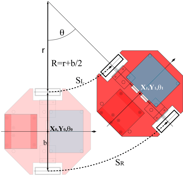
We need to know the position of the robot in real time, that means every small sampling time (10 ms is good) we need to recalculate the distance the robot traveled and the angel it did to calculate it's new position. After that we add this position to last calculated position and so on. just like we did with the guy.

The next diagram will explain how to deal with an Odometry in real time with a two wheeled robot using quadrature encoders.

The next code explaining how to implement Odometry in real time in an arduino.
In this code I used a software interrupt of 120ms (toooo much) get more assured that arduino is not for real time application

  l=0.5*(positionRight+positionLeft);
  Theta=positionRight-positionLeft;
  vitesse=l-lastL;
  lastL=l;
  Theta%=2292; //2292 is the number that corresponds to 2*pi
  double Theta_r=(double)Theta*0.002734;//Theta in radian
  deltaX=-vitesse*sin(Theta_r);
  deltaY=vitesse*cos(Theta_r);
  x+=deltaX;
  y+=deltaY;


Cheers :)


on Saturday, October 13, 2012
Have you ever wanted to do the same thing at the same time to win more time?! Cleaning the house while doing your homework :D that would be very helpful.
Working with embedded systems made crucial to deal with different tasks at the same time while having (most of the time) only one CPU that can handle only one task at a time.
To schedule between different tasks, embedded systems use RTOS (real time operating systems) which is in same how a little software is responsible to manage all the different tasks that want to use the CPU.

I found lately a wonderful tool to programme STM32 microcontrollers which is CoIDE from Coocox. It's based on the eclipse which makes programming the STM32 a lovely journey you don't want to miss.
 You can download Cocenter from here which contains all the other great software that come with CoIDE like CoOS which is a free RTOS that we will use it in this Tutorial.


So... Our mission is to blink a led in an infinite task and to watch for the value of the button in an other task.
I used the STM32 discovery board that contains an STM32F100RB.


After creating a project in your CoIDE, make sure to add the GPIO, RCC and CoOS libraries from the repository.

#include "stm32f10x.h"
#include "stm32f10x_gpio.h"
#include "stm32f10x_rcc.h"
#include <CoOs.h>

#define STACK_SIZE_DEFAULT 512

OS_STK task1_stk[STACK_SIZE_DEFAULT];
OS_STK task2_stk[STACK_SIZE_DEFAULT];

void initializeBoard(){

        GPIO_InitTypeDef GPIO_InitStructure_Led;
        GPIO_InitTypeDef GPIO_InitStructure_Button;

        RCC_APB2PeriphClockCmd(RCC_APB2Periph_GPIOC,ENABLE);//for LEds
        RCC_APB2PeriphClockCmd(RCC_APB2Periph_GPIOA,ENABLE);//for buttons

        GPIO_InitStructure_Led.GPIO_Pin = GPIO_Pin_8 | GPIO_Pin_9;
        GPIO_InitStructure_Led.GPIO_Mode = GPIO_Mode_Out_PP;
        GPIO_InitStructure_Led.GPIO_Speed = GPIO_Speed_50MHz;

        GPIO_InitStructure_Button.GPIO_Pin = GPIO_Pin_0;
        GPIO_InitStructure_Button.GPIO_Mode = GPIO_Mode_IN_FLOATING;
        GPIO_InitStructure_Button.GPIO_Speed = GPIO_Speed_50MHz;

        GPIO_Init(GPIOC,&GPIO_InitStructure_Led);
        GPIO_Init(GPIOA,&GPIO_InitStructure_Button);

}

void task1 (void* pdata){
        while(1){
                GPIO_WriteBit(GPIOC,GPIO_Pin_8,Bit_SET);
                CoTickDelay (10);
                GPIO_WriteBit(GPIOC,GPIO_Pin_8,Bit_RESET);
                CoTickDelay (10);
        }
}

void task2 (void* pdata){
        int i;
        while(1){
                i = GPIO_ReadInputDataBit(GPIOA,GPIO_Pin_0);
                GPIO_WriteBit(GPIOC,GPIO_Pin_9,i);
        }
}

int main(void)
{
        initializeBoard();
        CoInitOS();
        CoCreateTask(task1,0,0,&task1_stk[STACK_SIZE_DEFAULT-1],STACK_SIZE_DEFAULT);
        CoCreateTask(task2,0,1,&task2_stk[STACK_SIZE_DEFAULT-1],STACK_SIZE_DEFAULT);
        CoStartOS();
    while(1);
}


on Tuesday, September 25, 2012
on Friday, August 24, 2012


In this class we learned the final type of rotations : the point rotation
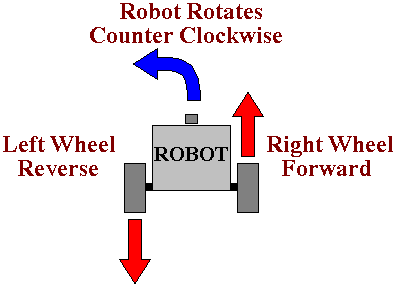
We need this kind of rotation when the robot must change its angle without changing its position in other words the robot rotate itself.
To make a robot turn a point rotation the wheels must rotate with the same speed but with different directions
This kind of rotation is very helpful in sharp angles <30°
To illustrate this kind of rotation we made a circuit which look like the heart beat:
The center of the robot must follow the circuit with no tolerance.

To apply a point rotation with the nxt-g just drag the steering to the extreme right or left then set the desired duration.


The second type of rotation that we will handle is parallel rotation:

This is the most common way of rotation for four wheels vehicles like cars.
The main idea is to turn the two wheels with different speed, so for a period of time the distance traveled by the faster wheel is more than the slower wheel as a result we don’t have straight movement but curve movement.
To apply this kind of rotation in a bidirectional robot like we have we used this circuit.

The circuit is very similar to a circle.
Ls will try to apply the swing rotation in this circuit but they will find it very painful, the great surprise I had that ls find by themselves the solution which lays in the Steering parameter we already see in the move block which is responsible for turning a bidirectional robot like a bicycle (well this is the example I used may be you will find better examples :=))

You can try other circuit like a snake body circuit for example.


Turning your robot is a crucial and standard task while commanding your robot to move, it is very rare to find a circuit with no turns.)
For bidirectional robot like the taskbot we made there are three possible ways of rotations;
Swing rotation
Parallel rotation
Point rotation
In this class we will talk about the swing rotation:
This kind of rotation is the simplest the main idea is when you want to turn left or right just stop a wheel and let the other wheel keep running.

For example, if we want to turn right, all what we have to do is to stop the right  and command the left wheel to move so the robot will turn right.
If we want to turn left,.. I guess you got it J
This kind of rotation is mainly used for turns like 90° or less in a straight circuit (a circuit with no curves)
To illustrate this example you should made a circuit like bellow and then ls will create the algorithm needed to follow this circuit.

First ls should create their first flowchart so you will help them:

To create a swing rotation using nxt-g put 2 move blocks.
In the first move block you select one portàthe motor witch you want to block or stop
Next of it in the second move block select one port -> the motor witch you want to run
on Sunday, August 19, 2012
In this class we discussed one of the major problems in the mobile robots field witch is as the title says how to move your robot to an exact distance nothing more and nothing less.

Moving the robot to a known position is crucial in some cases, so in this class ls will learn how to convert wanted distance measured with a measuring tool to an order in the move block.

Every group take a wheel and move the wheel from a start point one rotation. Then move the wheel from the exact start point twice.
ls will know that the number of rotation traveled by the wheel is one responsible for how much the robot will move.
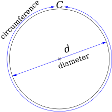
Now try with smaller wheel do one rotation then 2, ls will notice that even the wheel traveled the same unit it doesn't travel the same distance as the bigger wheel so here you introduce to them the principal of calculating the circumference.

Measuring circumference of the taskbot wheel:
Start by measure the circumference of the robot practically using standard measuring tools.
Then write the result for each group.
ls will notice that the results are not the same so there are an incertitude factor during the measuring.
The solution is to calculate the circumference using already knowing informations:

We used the famous formula : ( D = 2.25 inche/5.751 centimeters , Pi = 3.14)
C = Pi * D
C= 17.49 cm

A mission to 59.5 cm:
This is an example to demonstrate this new way for using the move block. 
So our objective is that the robot go exactly 59.5 cm 
We have to calculate the number of rotations needed to put in the move block.
The operation is simple: we divide the desired distance on the circumference of the wheel.
number of rotations needed = 59.5/17.49 = 3.4
So the number of rotations needed is 3.4